25
8024638/AE00/V1-0/2019-09| SICK S E R V I C E M A N U A L | MCS200HW
Subject to change without notice
MAINTENANCE 3
3.4.4 Replacing the non-return valve on the cell inlet filter
The non-return valve can be replaced with the cell fitted.
1 Disconnect the MCS200HW power supply.
2 Let the MCS200HW cool down.
3 Loosen the fastening screws of the cell cover on the right and left with a Phillips screw-
driver (4 pieces).
1 Open the cell cover (see Chapter “Working on the cell”, page 14).
2 Loosen the test gas connection with a jaw wrench (see Fig. 15 “Cell inlet filter, hose con-
nections”, page 22).
3 Remove the non-return valve and 90-degree bracket together.
.
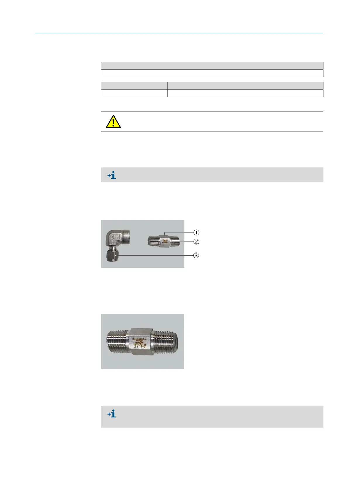
Fig. 21: Non-return valve and 90-degree bracket, new
Fig. 22: Non-return valve, arrow marking, flow direction
4 Insulate the new non-return valve:
▸ Wrap both ends with Teflon tape.
▸ Leave the first two threads free.
Tools required
Jaw wrench, size 14
Spare parts set No. Contents
2099679 Cell inlet filter and non-return valve
DANGER: Risk of burns due to hot surface.
Allow the MCS200HW to cool down before carrying out any work.
Do not remove the screws, only loosen them.
1Non-return valve
2 Flow direction arrow marking
3 90-degree bracket
Observe winding direction:
Attach the Teflon tape so that it runs in the direction of rotation/threading when
screwing in.

 Loading...

