59
8024638/AE00/V1-0/2019-09| SICK S E R V I C E M A N U A L | MCS200HW
Subject to change without notice
REPAIRS 5
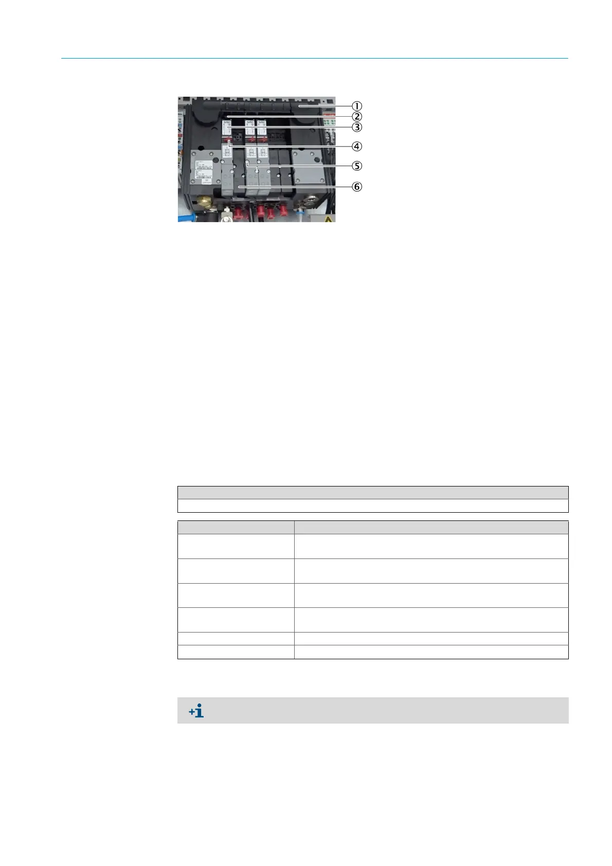
Fig. 71: Valve
7 Use the removal lever to pull the valve out to the front.
8 Insert a new valve into the guide rail and screw tight.
9 Align the red valve screw horizontally.
10 Open the instrument air.
11 Disconnect the MCS200HW power supply.
12 Connect the bus cable on the CAN node.
13 Connect the power supply of the CAN node at the 24V power supply unit.
14 Connect the MCS200HW power supply.
5.1.5 Replacing the IO module
1 Disconnect the MCS200HW power supply.
2 Remove the leads from the IO module.
3 Use the orange holder to pull the IO module out to the front.
1Valve manifold
2Removal lever
3Valve
4Valve screw
5Fastening screw
6 Placeholder
Tools required
Phillips screwdriver
Spare parts set No. Contents
2098608
Digital input module, 4 channels, positive switching, contact load
24
V DC, 4.5 mA for actuator application
2098609
Digital input module, 4 channels, positive switching, contact load
24
V DC, 4.5 mA for potential-free contact
2098610
Digital output module, 4 channels, positive switching, galvanically
isolated, contact load 24 V DC, 10 mA
2098611
Digital output module, 2 channels as changeover contacts, potential-
free, 2 W 125 V 0.5 A
2098612 Analog input module, 2 channels, 0 - 20 mA
2098613 Analog output module, 4 channels, 0 - 20 mA
Document the position of the leads before removing them, e.g. with a photo.
 Loading...


