58
8024638/AE00/V1-0/2019-09| SICKSERVICE MANUAL | MCS200HW
Subject to change without notice
5 REPAIRS
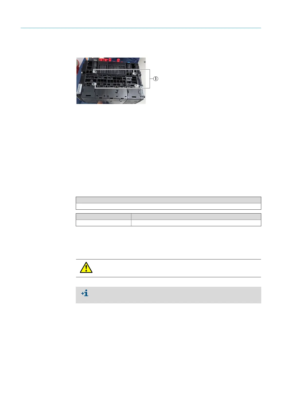
1 Before inserting, check the horizontal alignment of the locking devices on the rear
side.
Fig. 70: Valve manifold, rear side
2 Insert the valve manifold straight from the front and let it engage.
3 Screw the valve manifold tight.
10 Connect the hoses.
11 Open the instrument air.
12 Disconnect the MCS200HW power supply.
13 Connect the bus cable on the CAN node.
14 Reconnect the power supply of the CAN node on the 24V power supply unit.
15 Connect the MCS200HW power supply.
5.1.4.2 Replacing the valve
1 Disconnect the MCS200HW power supply.
2 Disconnect the bus cable on the CAN node (see Fig. 68 “CAN node, detail”, page 56).
3 Disconnect the power supply of the CAN node at the 24V power supply unit.
4 Connect the MCS200HW power supply.
5 Close off instrument air provided by the customer.
6 Loosen the valve fastening screws with a Phillips screwdriver (2 pieces).
1Valve manifold locking
Tools required
Phillips screwdriver
Spare parts set No. Contents
2099915 Valve
The power supply must be restored to maintain the device heating. Flue gases can
damage the cooled device when the power supply is switched off and the instrument air
is closed off.
Alternative: Relieve the pressure regulator.
▸
Turn counterclockwise to relieve.
▸
Increase pressure by turning clockwise (check display).

 Loading...

