119
8024638/AE00/V1-0/2019-09| SICK S E R V I C E M A N U A L | MCS200HW
Subject to change without notice
REPAIRS 5
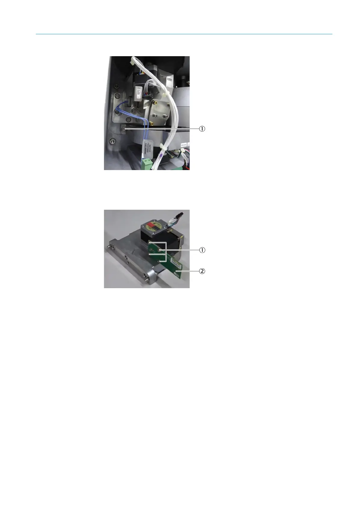
Fig. 183: Filter wheel housing 3, fastening screw, left
3 Remove the filter wheel housing.
Fig. 184: LPMS03 detector circuit board
4 Disconnect the detector cable.
5 Loosen the fastening screws of the LPMS03 detector circuit board with a Phillips screw-
driver (4 pieces).
6 Screw the new LPMS03 detector circuit board tight.
7 Connect the detector cable to the LPMS03 detector circuit board.
8 Insert filter wheel housing 3 into the sender/receiver unit and screw tight.
▸ The filter wheel housing cover points upwards.
9 Connect the lug connection of the filter wheel housing to the LPMS04 circuit board.
10 Close the sender/receiver unit cover and screw tight.
11 Connect the MCS200HW power supply.
12 Perform optical adjustment (see Chapter “Performing optical adjustment”, page 103).
13 Reset the reference energy (see Chapter “Resetting the reference energy”, page 91).
14 Perform zero point adjustment (see Chapter “Adjusting the zero point”, page 128).
1Fastening screw
1Fastening screw
2LPMS03 detector circuit board

 Loading...

