Service
SICAM RTUs, SICAM AK 3 User Manual 209
DC2-028-2.03, Edition 07.2016
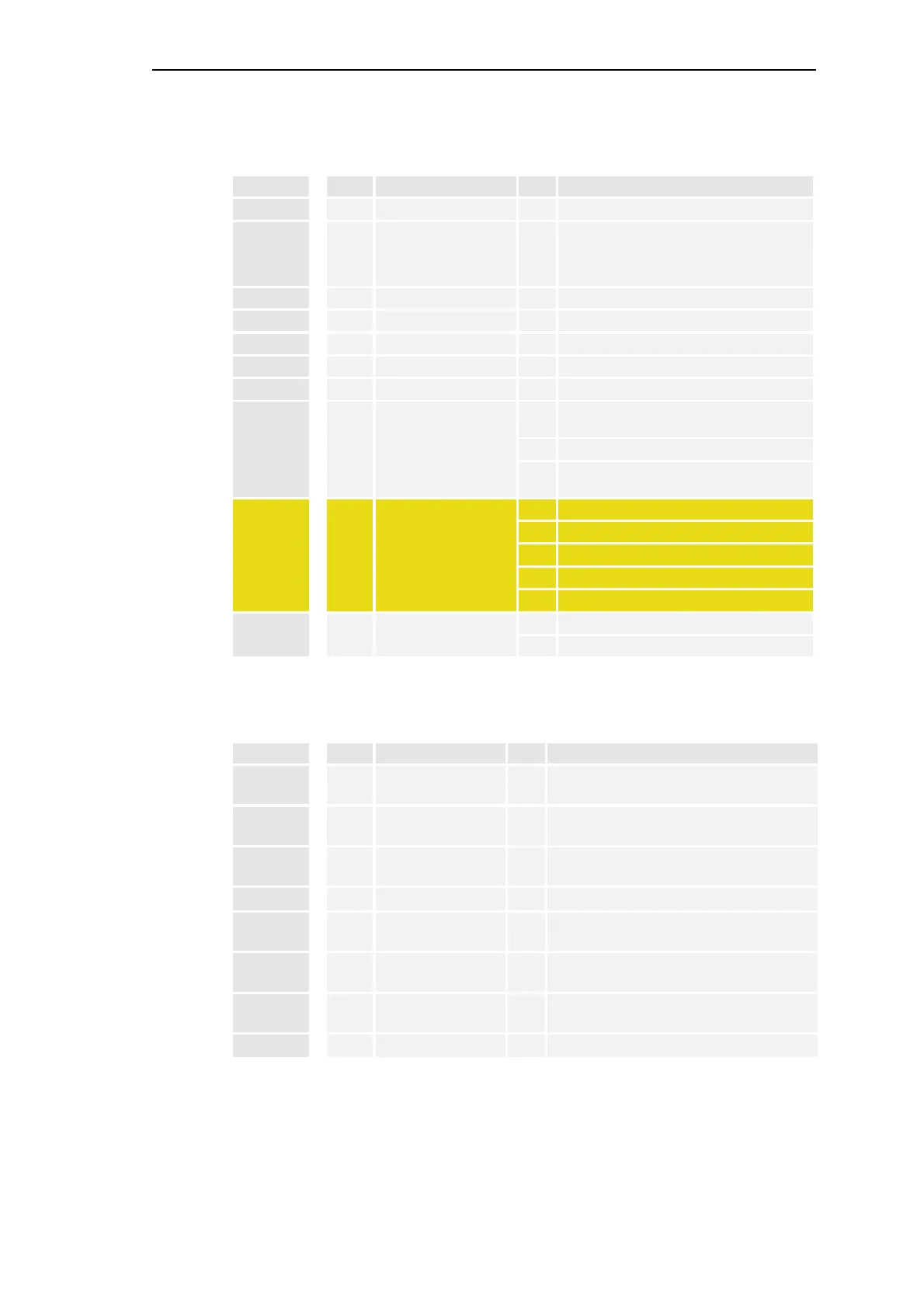
System Display Elements
Name Color Function LED Meaning
RY yellow Ready
˜
Master control element ready
ER red Error
˜
• Sum error (internal error, external error,
warning, module failure, failure; includ-
ing peripheral elements)
• Startup
W yellow Warning
˜
Warning
BBD yellow Board breakdown
˜
Module failure
INT yellow Internal error
˜
Internal error
EXT yellow External error
˜
External error
ACT yellow CPU active
˜
CPU active
CPY yellow Copy
§
Parameters being loaded into the flash
PROM
˜
firmware being loaded
V
Check checksum of parameter and firmware
files on the flash card
SF
*)
˜
RUN
™
STOP
§
TEST
™
KILL
™
Startup
HLT yellow Halt
§
Firmware shut down
˜
Module shut down
*)
only valid for CP-2019 with Safety-Firmware
Display elements of the local Ethernet protocol elements
Name Color Function LED Meaning
LK X0 yellow
PRE0 Link
˜
Protocol element 0, physical connection to
switch/remote station
PK X0 yellow
PRE0 Packet
˜
Protocol element 0, activity on trans-
mit/receive direction
ACT0 yellow
PRE0 Active
˜
Protocol element 0, interface active - redun-
dancy
ER0 yellow
PRE0 Error
˜
Protocol element 0, Error on interface
LK X1 yellow
PRE1 Link
˜
Protocol element 1, physical connection to
switch/remote station
PK X1 yellow
PRE1 Packet
˜
Protocol element 1, activity on trans-
mit/receive direction
ACT1 yellow
PRE1 Active
˜
Protocol element 1, interface active - redun-
dancy
ER1 yellow
PRE1 Error
˜
Protocol element 1, Error on interface

 Loading...


