Parameter ID Adjustment range Factory set‐
ting
Unit Description
p100 0 = FBLOCK + Bus
1 = FBLOCK + relay
0 — Default command mode:
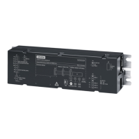
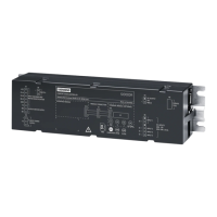
For the ATD420W, ATD430W control units the com‐
mand input via the bus system is activated in the de‐
fault setting -> parameter p100 = 0. This means that
the FBLOCK drive orders can only be executed in the
drive state "S4: Z_MODE" (see Figure 4-4 State graph
control unit (Page 163)).
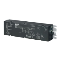
For the ATD401W control unit with relay module, no
command mode is possible via the bus system. For
this control unit variant, parameter p100 = 1 must
always be set. Otherwise, the control unit cannot be
controlled via the digital inputs.
r200 1 … 65535
0 = Checksum invalid
— — Checksum for the default parameters (see Checksum
parameters (as of V1.12) (Page 77))
r201 1 … 65535
0 = Checksum invalid
— — Checksum for the learn run parameters (see Check‐
sum parameters (as of V1.12) (Page 77))
r202 0 … 65535 — — Change counter for the default parameters
(see Checksum parameters (as of V1.12) (Page 77))
r203 0 … 65535 — — Firmware version
The version is output as "MajorVer*100 + MinorVer".
e. g. rmware version "1.13.1234" is output as "113".
r204 0 = Checksum invalid
1 = Checksum valid
— — Validity of the checksum for the default parameters
r200, r201.
p2080 0 … 65535 FFFF (hex) — DCMD masking eldbus
Each bit in the mask lters the corresponding bit in
TSW1:
0: CMD bit is not allowed to pass
1: CMD bit is allowed to pass
p2081 0 … 65535 FFFF (hex) — DCMD masking FBLOCK
Each bit in the mask lters the corresponding bit in
TSW1:
0: CMD bit is not allowed to pass
1: CMD bit is allowed to pass
Controllers
5.9 Operation and conguration of the control unit
ATD4xxW for industrial applications
190 System Manual, 06/2022, A5E51901827B AA

 Loading...


