EasyManuals Logo

Siemens SIMATIC HMI series User Manual

Siemens SIMATIC HMI series
288 pages
To Next Page IconTo Next Page
To Previous Page IconTo Previous Page
Page #19 background imageLoading...
Page #19 background image
Overview
1.4 Connection boxes
Mobile Panels 2nd Generation
Operating Instructions, 09/2018, A5E33876626-AC
19
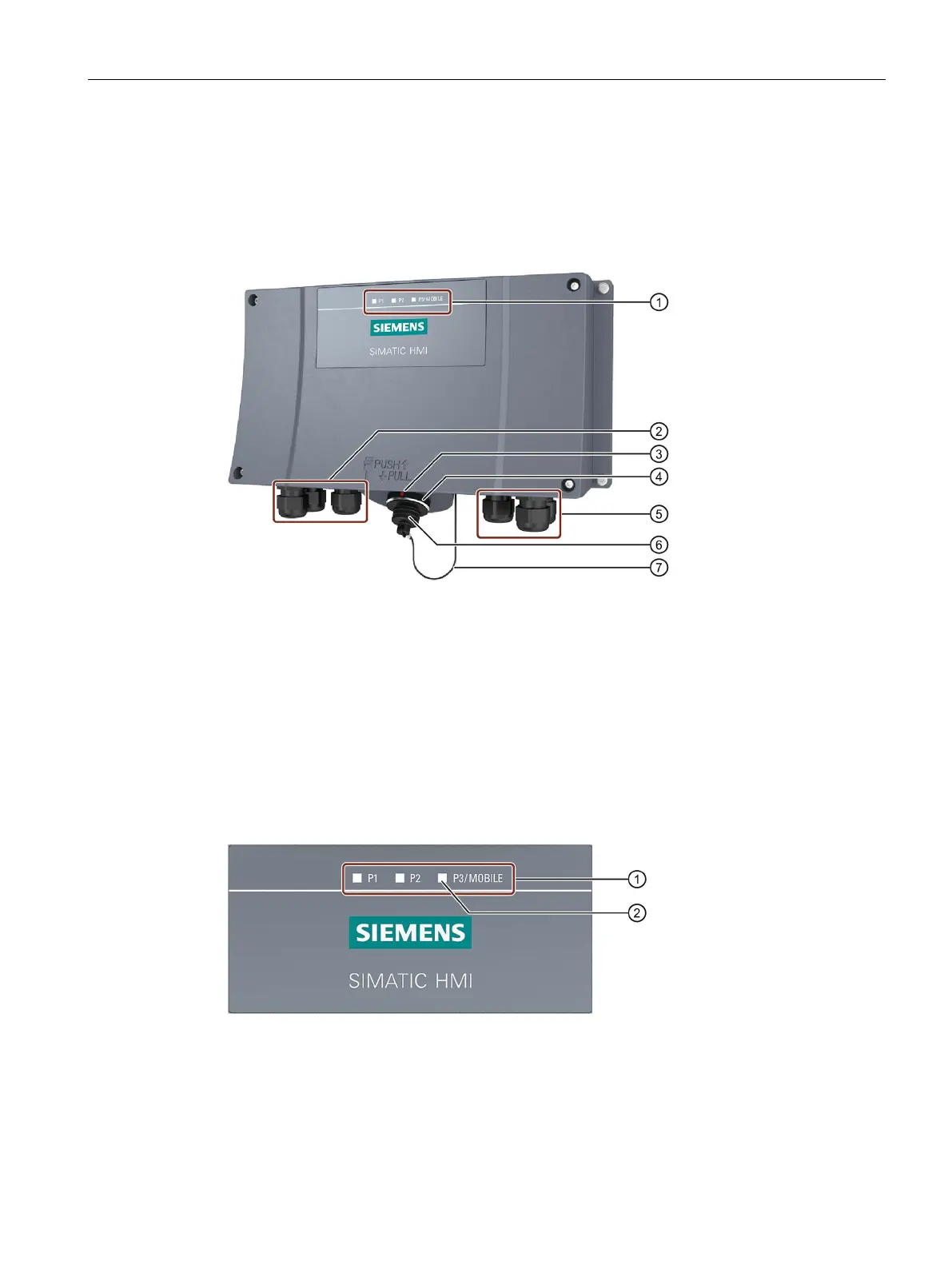
Connection box standard and connection box advanced
The figure below shows the connection box standard or the connection box advanced. The
connection box advanced also features:
Real-time Ethernet
F-signal transmission
LED display
Screw glands for the data cables
Positioning mark
There is also a red positioning mark on the connecting cable. Align this mark with the
positioning mark on the connection box when connecting.
Connection socket for the connecting cable
Screw glands for power supply cables and F-signal cables
Cover of the connection socket
Safety strap
There are three LEDs on the front of the connection box that indicate the status of
communication.
LED display of the three Ethernet ports:
P1: Fast Connector X1
P2: Fast Connector X2
P3: Connection socket for the Mobile Panel
LED

Table of Contents

Other manuals for Siemens SIMATIC HMI series

Questions and Answers:

Question and Answer IconNeed help?

Do you have a question about the Siemens SIMATIC HMI series and is the answer not in the manual?

Siemens SIMATIC HMI series Specifications

General IconGeneral
SeriesSIMATIC HMI
CategoryControl Panel
Display TypeTFT LCD
Touch ScreenYes (resistive or capacitive, depending on model)
ProcessorVaries by model (e.g., ARM-based processors)
StorageVaries by model (e.g., Flash memory, microSD card slot)
Communication InterfacesEthernet, USB
Protection ClassIP65 (front panel), depending on model
Operating Temperature0 to 50°C, -20 to 60°C
Power Supply24 V DC
Memory128 MB, 256 MB

Related product manuals