EasyManuals Logo

Siemens SIMATIC HMI series User Manual

Siemens SIMATIC HMI series
288 pages
To Next Page IconTo Next Page
To Previous Page IconTo Previous Page
Page #63 background imageLoading...
Page #63 background image
Installing system components
3.6 Connecting the connection box
Mobile Panels 2nd Generation
Operating Instructions, 09/2018, A5E33876626-AC
63
Connection graphic
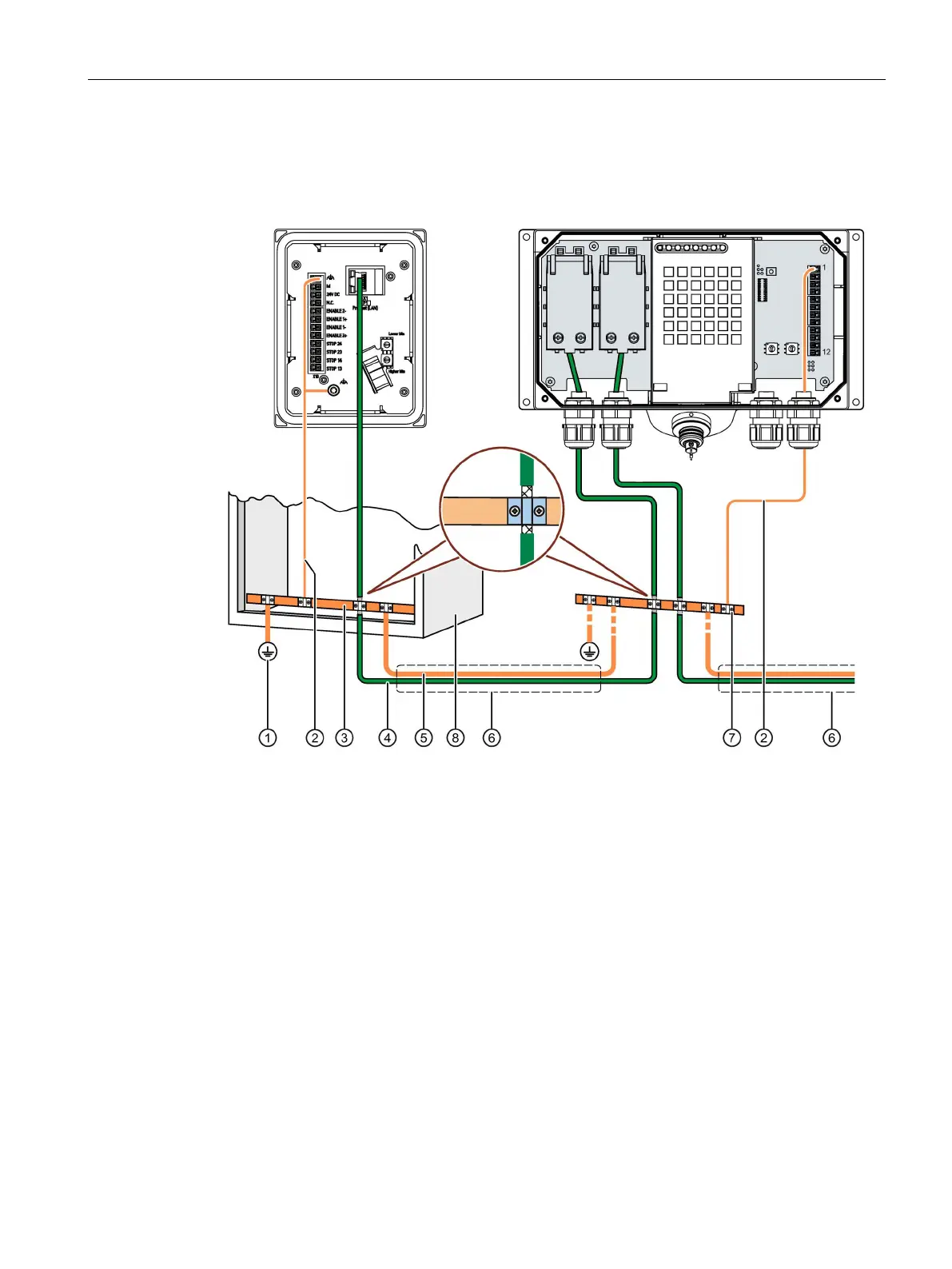
The figure below shows how to connect the equipotential bonding of the connection boxes to
the equipotential busbars.
Ground connection
Equipotential bonding conductor, cross-section 1.5 mm
2
Equipotential busbar for equipotential bonding cables, grounding connection and shield support
of the data cables
Ethernet cable
Equipotential bonding conductor, cross-section ≥ 16 mm
2
Parallel routing of the equipotential bonding conductor and data cable
Cable clip
Control cabinet

Table of Contents

Other manuals for Siemens SIMATIC HMI series

Questions and Answers:

Question and Answer IconNeed help?

Do you have a question about the Siemens SIMATIC HMI series and is the answer not in the manual?

Siemens SIMATIC HMI series Specifications

General IconGeneral
SeriesSIMATIC HMI
CategoryControl Panel
Display TypeTFT LCD
Touch ScreenYes (resistive or capacitive, depending on model)
ProcessorVaries by model (e.g., ARM-based processors)
StorageVaries by model (e.g., Flash memory, microSD card slot)
Communication InterfacesEthernet, USB
Protection ClassIP65 (front panel), depending on model
Operating Temperature0 to 50°C, -20 to 60°C
Power Supply24 V DC
Memory128 MB, 256 MB

Related product manuals