Installing system components
3.6 Connecting the connection box
Mobile Panels 2nd Generation
Operating Instructions, 09/2018, A5E33876626-AC
65
1. For connection box standard and connection box advanced: Thread the cables through
the corresponding screw glands.
2. When you use flexible cables, place a wire end ferrule on each wire to be connected.
3. Insert the wire ends into the associated spring-loaded terminal as shown in the figures
below.
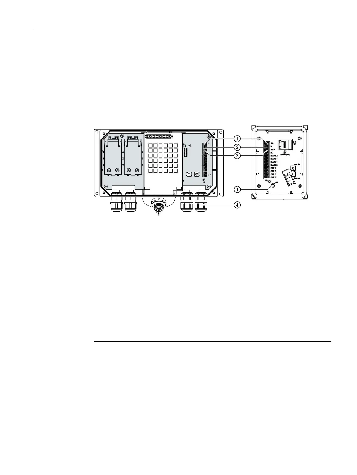
The figure below shows the contacts to be connected to the X10 terminal of the
connection box and the cable glands for cable entry.
Connection for functional ground
4. Connect the equipotential bonding conductor to the equipotential busbar.
5. Connect the equipotential bonding conductor to the terminal for the functional ground of
the connection box.
Connect the equipotential bonding conductor of the connection box as described in the
section "Equipotential bonding of connection boxes (Page 62)".
Note
Applies to floating system design
:
Connect the terminal for GND
24 V from the 24 V power supply output to equipotential
bonding for uniform reference potential.
6. For connection box standard and connection box advanced:
When all the required work has been completed in the connection box, close it.
 Loading...


