Installing system components
3.6 Connecting the connection box
Mobile Panels 2nd Generation
Operating Instructions, 09/2018, A5E33876626-AC
71
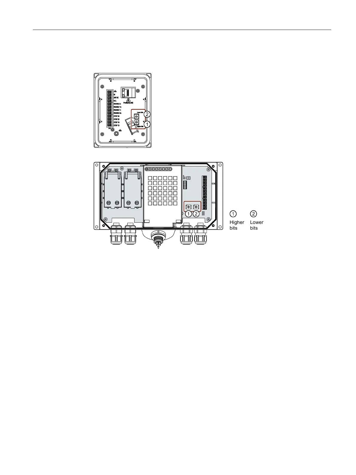
● Position of the rotary coding switch in the connection box compact
● Position of the rotary coding switch in the connection boxes standard and advanced
● For connection box standard and connection box advanced: The connection box is open.
● The connection box is disconnected from its power supply.
● A suitable tool made of plastic
1. Rotate the arrows of the rotary coding switch to the required hexadecimal value using a
suitable tool.
Values from "00" to "FF" (0 to 255 in decimal form) can be set with the rotary coding
switches.
When setting the box ID:
– Use the value "00" only for the "Stop button evaluated by safety relay" operating
mode.
– The value "FF" (255) is reserved and may not be used.
 Loading...


