Installing system components
3.2 Mounting the connection box compact
TP1000F Mobile RO
36 Operating Instructions, 08/2017, A5E39831415-AA
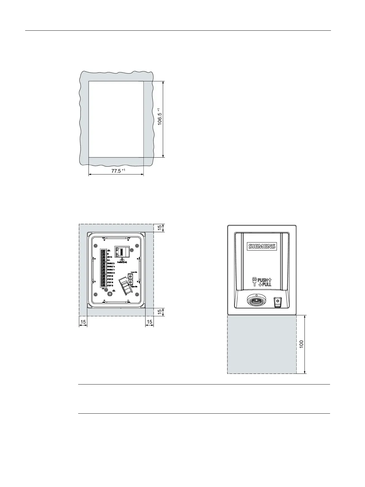
The following illustration shows the dimensions for the mounting cut-out, all dimensions in
mm:
The connection box is self-ventilated. To ensure self ventilation in the control cabinet and be
able to connect the connecting cable without any problems, you need the clearance
indicated in the figures below, all dimensions in mm:
Note that in addition to the mounting depth of
the connection box, a rear clearance is r
e-
based on the leads and plugs used.
Note
Ensure that the maximum ambient temperature as detailed in "
Operating Conditions
160)" is not exceeded when installing the device in closed enclosure.
Allow for 80 mm of clearance below the connection box to enable you to easily plug in the
connecting cable.

 Loading...


