Installing system components
3.6 Connecting the connection box
TP1000F Mobile RO
Operating Instructions, 08/2017, A5E39831415-AA
57
Connecting cables for a hardwired F-system
The signals for the emergency stop / stop button and the enabling button must be wired for a
hardwired F-system.
Length of the data cables to the connection box
If the permissible length of the data cables and signal cables between a connection box
and the plant is exceeded, malfunctions may occur. Keep the permissible length of ≤ 30 m
for cables to the connection box.
● The connection box standard or advanced is open.
● The power cable wires have been stripped by 6 mm.
● Wire end ferrules ∅ 0.5 mm.
1. Connection boxes standard and advanced:
Thread the cables through the corresponding screw glands.
2. Place a wire end ferrule on each wire to be connected.
3. Insert the wire ends into the corresponding spring-loaded terminal as shown in the figures
below.
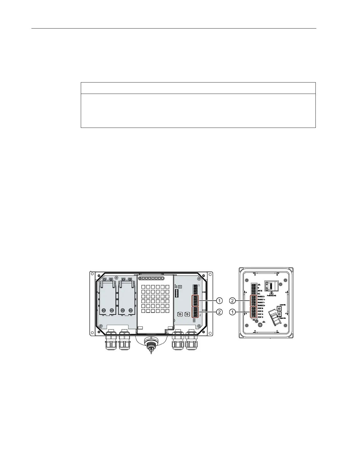
The figure below shows the terminals to be connected on the connection box.
Terminal for the emergency stop / stop button
Terminal for the enabling button

 Loading...


