6 Assi
nin
Parameters to the Control and the PLC Pro
ram
6
03.96
6.9 Axes and spindles
6-110
Siemens AG 2000 All Rights Reserved
SINUMERIK 840D Installation and Start-Up Guide (IAD) – 04.00 Edition
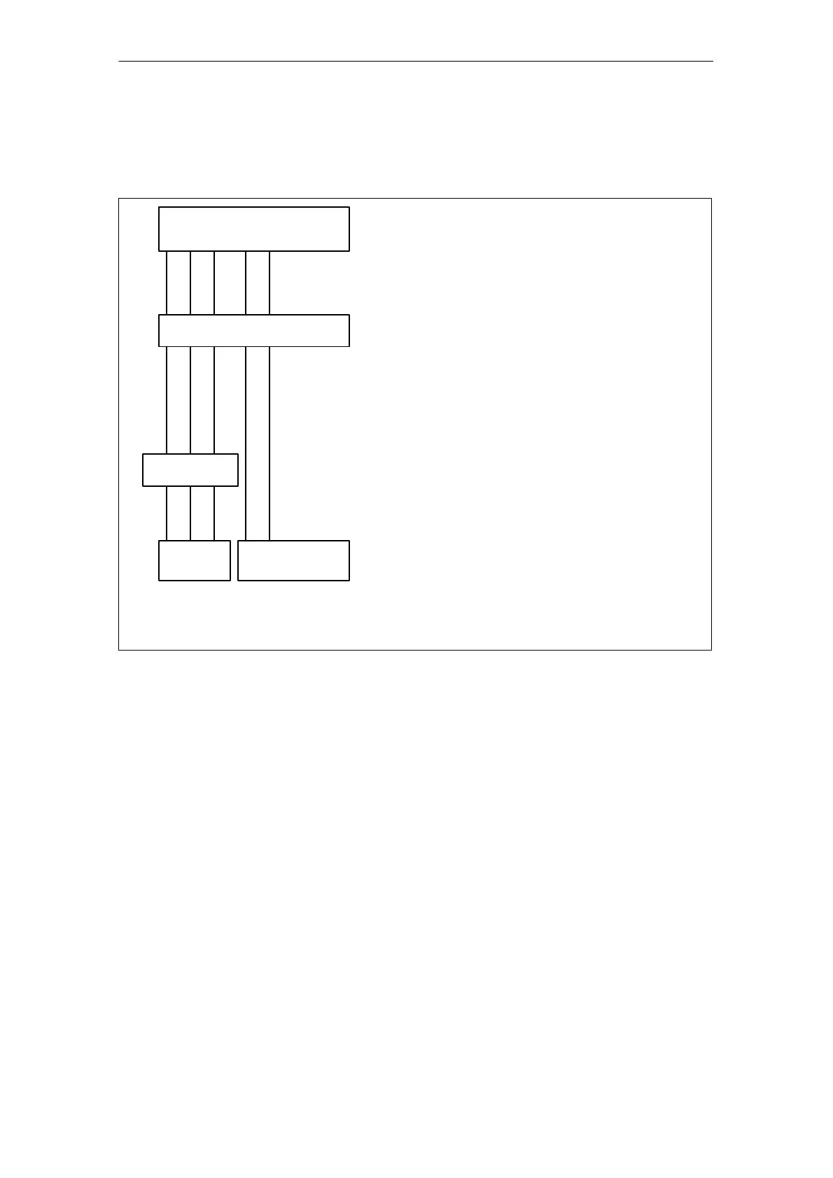
In a program run, the coordinates that are not assigned via MD 20060/
MD 20050 are always mapped directly onto the axes of the channel (in the
milling machine example, axes A and C).
Machine axis no. for channel
1 2 3 4 5
A C
Axis name in channel (addition. axes)
X Y Z
GEO axis
Assignment of
GEO axes
A C
Additional axes
MD 20070: AXCONF_MACHAX_USED
Machine axes used in channel
AXCONF_MACHAX_USED[0]=1
AXCONF_MACHAX_USED[1]=2
AXCONF_MACHAX_USED[2]=3
AXCONF_MACHAX_USED[3]=4
AXCONF_MACHAX_USED[4]=5
MD 20080: AXCONF_CHANAX_NAME_TAB
Name of additional axes in channel (for use in
part program)
AXCONF_CHANAX_NAME_TAB [0]=
AXCONF_CHANAX_NAME_TAB [1]=
AXCONF_CHANAX_NAME_TAB [2]=
AXCONF_CHANAX_NAME_TAB [3]=A
AXCONF_CHANAX_NAME_TAB [4]=C
MD 20050: AXCONF_GEOAX_ASSIGN_TAB
Assignment of GEO axes to channel axes.
AXCONF_GEOAX_ASSIGN_TAB [0]=1
AXCONF_GEOAX_ASSIGN_TAB [1]=2
AXCONF_GEOAX_ASSIGN_TAB [2]=3
X to X, Y to Y, Z to Z
Name of GEO axes
MD 20060: AXCONF_GEO_AX_NAME_TAB[0]=X
MD 20060: AXCONF_GEO_AX_NAME_TAB[0]=Y
MD 20060: AXCONF_GEO_AX_NAME_TAB[0]=Z
Fig. 6-4 Example of a milling machine: 4 axes + spindle/C axis
The names defined in MD 10000: AXCONF_MACHAX_NAME_TAB or the as-
sociated index are used for
S accessing axis-specific machine data (loading, saving, displaying)
S reference point approach G74
S measurements
S fixed point approach G75
S traversing commands from PLC
S display of axis-specific alarms
S display of actual-value system (machine-related)
S DRF handwheel function

 Loading...


