6 Assi
nin
Parameters to the Control and the PLC Pro
ram
6
03.96
6.10 Linear motors (1FN1 and 1FN3 motors)
6-170
Siemens AG 2000 All Rights Reserved
SINUMERIK 840D Installation and Start-Up Guide (IAD) – 04.00 Edition
Scanning head
Rating plate
Scale
+
Fig. 6-36 Calculating the count direction of Heidenhain measuring systems
2. Renishaw measuring systems (e.g. RGH22B)
The Renishaw RGH22B measuring system (graduations = 20 µm) has com-
patible connections with the Heidenhain products from serial number
G69289 onwards. The zero marker on earlier scanning head models cannot
be evaluated. Since the reference marker on the Renishaw RGH22B has a
direction-dependent position, encoder signals BID and DIR must be para-
meterized such that the reference marker is output in only one direction.
The direction (positive/negative) is dependent on the geometric configura-
tion on the machine and the reference point approach direction.
Table 6-24 Signal and pin assignments, routing on 1FN linear motor
Signal Cable
Circular
Connected to
co
or connector
12-pin
+5 V 0 V
BID black Pin 9 Reference marker in
both directions
Reference marker in
one direction
DIR orange Pin 7 Positive directions Negative direction
+5 V brown Pin 12
0 V white Pin 10
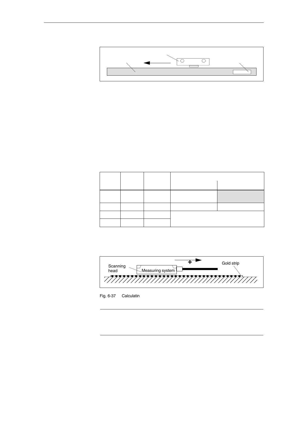
The count direction of the measuring system is positive if the scanning head
moves in the direction of the outgoing cable in relation to the gold strip.
ÌÌÌÌÌÌÌÌÌÌÌÌÌÌÌÌÌÌÌÌ
ÌÌÌÌÌÌÌÌÌÌÌÌÌÌÌÌÌÌÌÌ
Gold strip
Scanning
head
Measuring system
+
Fig. 6-37 Calculating the count direction of Renishaw measuring systems
Note
If the scanning head is mechanically coupled to the primary part, the
outgoing cable direction must be different. Otherwise invert the actual value!
04.0004.00

 Loading...


