Detailed description
2.6 Interface structure
Basic logic functions: PLC basic program solution line (P3 sl)
Function Manual, 11/2006, 6FC5397-0BP10-2BA0
35
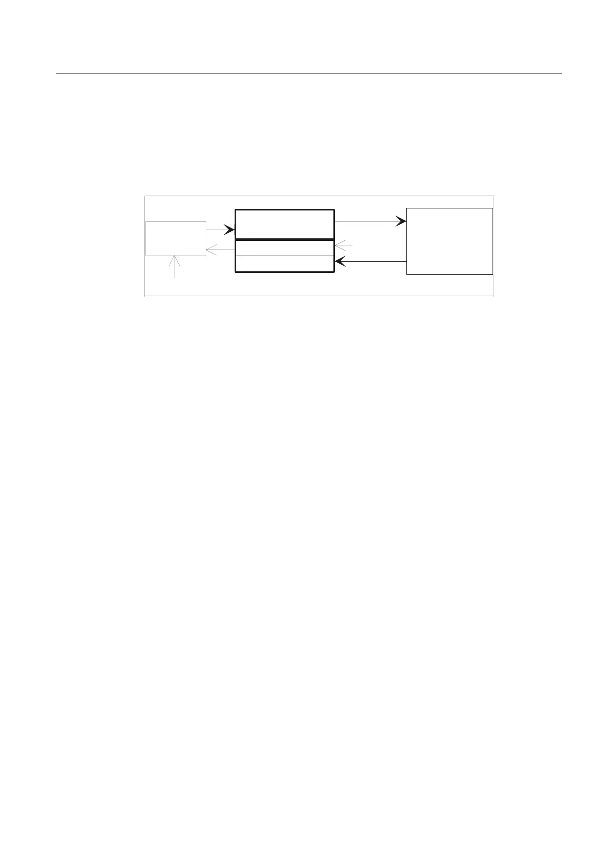
Signals PLC/Mode group
The operating mode signals set by the machine control panel or the HMI are transferred to
the operating mode group (BAG) of the NCK. On the 840D, these are valid for all NCK
channels. On 840D systems, several mode groups can optionally be defined in the NCK.
The mode group reports its current status to the PLC.
1&.
%DVLF3URJUDP
0&3
6HOHFWLRQ
0RGH
PRGHJURXS
*URXS
0RGH
+0,
$FWLYHPRGH
6HOHFWLRQVLJQDOVIURP+0,
0RGHVHOHFWLRQ
&RQWUROVLJQDOV
'%
%\WH
Figure 2-6 PLC/Mode group interface
Signals PLC/NCK channels
The signal groups below must be considered on the interface:
• Control/status signals
• Auxiliary/G functions
• Tool management signals
• NCK functions
The control/status functions are transmitted cyclically at the start of OB1. The signals
entered in the channelspecific interface by the HMI (HMI signals are entered by the PLC
operating system) are also transferred at this time if they have been defined on the HMI
operator panel, not on the MCP.
Auxiliary functions and G functions are entered in the interface data blocks in two ways.
First, they are entered with the change signals.
• M signalsM00 - M99 (they are transferred from the NCK with extended address 0) are also
decoded and the associated interface bits set for the duration of one cycle.
• For G functions, only the groups selected via machine data are entered in the interface
data block.
• S values are also entered together with the related M signals (M03, M04, M05) in the
spindlespecific interface. The axisspecific feedrates are also entered in the appropriate
axisspecific interface.
When the tool management (magazine management) function is activated in the NCK, the
assignment of spindle or revolver and the loading/unloading points are entered in separate
interface DBs (DB71 - 73)

 Loading...


