Detailed Description
2.5 Toolholder with orientation capability
Basic logic functions: Tool Offset (W1)
108 Function Manual, 11/2006, 6FC5397-0BP10-2BA0
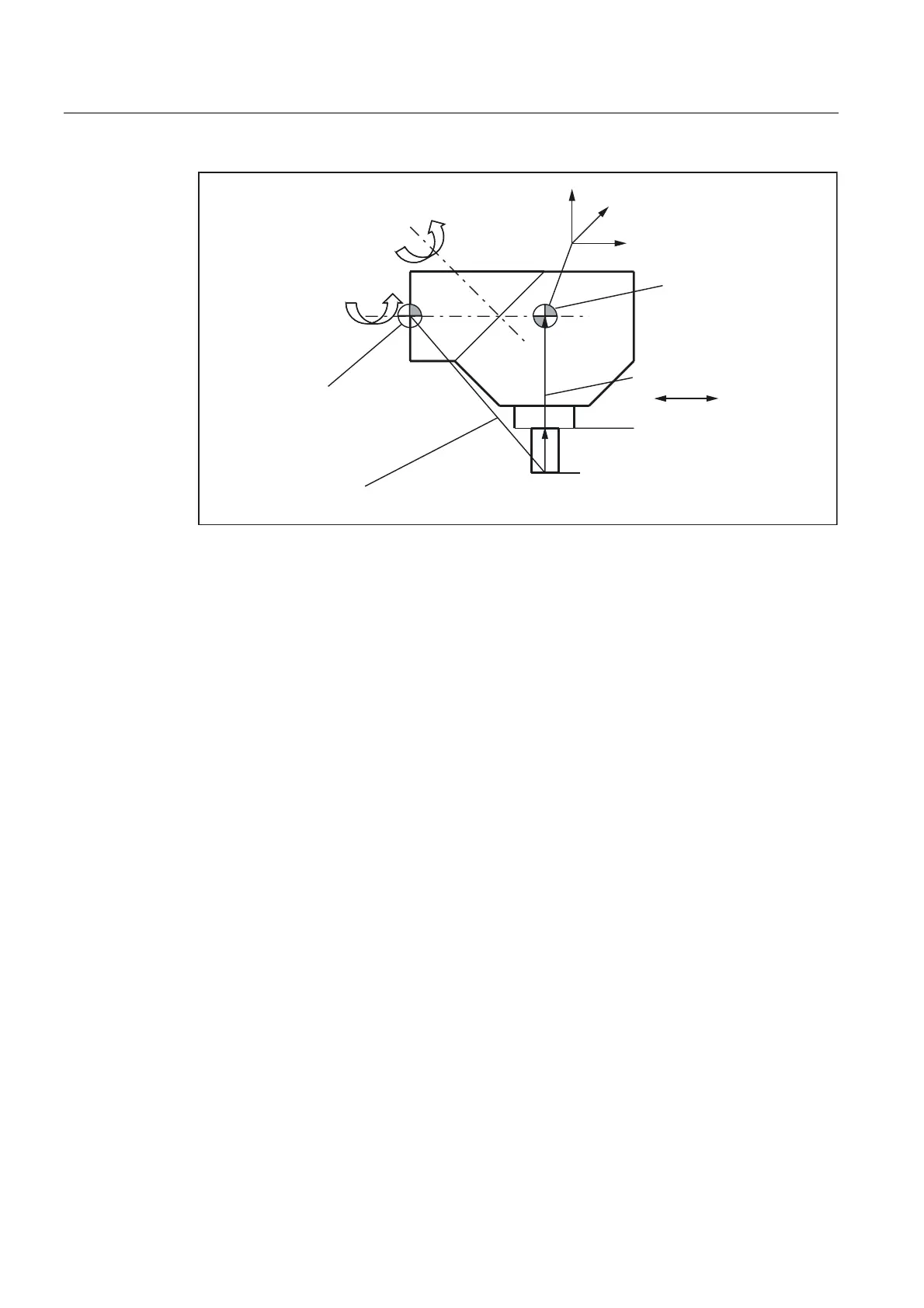
5HVXOWLQJWRROOHQJWKFRPSHQVDWLRQ
/HQJWK:HDU
7RROEDVHGLPHQVLRQ
7RROFDUULHUUHIHUHQFHSRLQW
$[LV
$[LV
7RROUHIHUHQFHSRLQW
[
]
\
PP
O
O
Y
Y
O
Figure 2-46 Assignment of the toolholder data
Suitable assumptions were made for the following values in the data block:
• The two rotary axes intersect at one point.
All components of l
2
are therefore zero.
• The first rotary axis lies in the x/z plane, the second rotary axis is parallel to the x axis.
These conditions define the directions of v
1
and v
2
(the lengths are irrelevant, provided
that they are not equal to zero).
• The reference point of the toolholder lies 200 mm in the negative x direction viewed from
the intersection of the two rotary axes.
This condition defines l
1
.

 Loading...


