PVA-3000 Reference Manual
December 2, 2019 Sifos Technologies
5.6.1. The DC Unbalance Impairment
PSE’s add power by applying DC voltage and inserting DC current to the center taps of two Ethernet pairs, either pairs
2 and 3 (referred to as ALT A) or to pairs 1 and 4 (referred to as ALT B). This means one pair has a common mode
voltage that can vary between 44 VDC and 57 VDC while another pair serves as a common mode reference at 0 VDC.
To deliver 30 watts at 50 VDC requires 600 mA of current that would ideally split evenly so that 300 mA would flow
on each conductor of a single twisted pair to the PD and return from the PD on each conductor of another pair.
Four factors can cause current injected in a primary center tap to not split evenly:
1. Unbalanced magnetic windings in the PSE
12. Uneven contact resistances in connecting hardware
13. Unbalanced conductor lengths in the LAN cabling to the PD
14. Unbalance magnetic windings in the PD
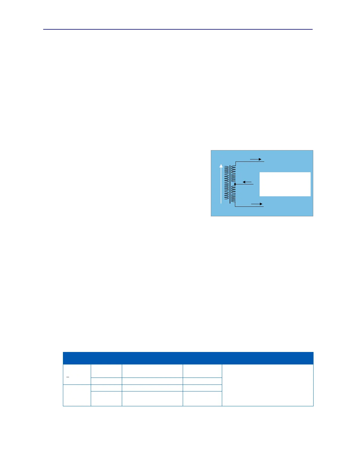
When DC current injected into a center tap is not split evenly between the two conductors, a DC bias (see I
bias
in
Figure 5.19) develops across the primary coil and affects the magnetic core in a direction dependent on the bias
polarity. As this DC bias increases, the magnetic core starts to
saturate meaning that AC currents required to convey
10/100/1000BaseT signals will become clipped and distorted. Low
frequencies are impacted more severely by this fixed core bias and
become attenuated relative to higher frequencies. It is for this
reason that the 100BaseTx standard requires open circuit inductance
(OCL) of the magnetic coils to exceed 350H in the presence of 8
mA of DC bias current. 100BaseTx, even without Power-over-
Ethernet (PoE) currents, can create DC biases on magnetics with
payload patterns that result in significant baseline wander. PoE
then adds a second potential cause of DC transformer bias, one that
scales with the amount of power delivered.
5.6.2. IEEE 802.3 DC Unbalance Requirements
In PoE, current flows out toward the PD on one twisted pair and returns to the PSE on a second twisted pair. As figure
5.18 indicates, DC unbalance current, I
unb
, is the magnitude difference in current flowing on each conductor of a
twisted pair.
The IEEE PoE specification, 802.3at, stipulates that a link supporting PoE have a maximum DC Resistance Unbalance
of 3% where DC Resistance Unbalance = (Conductor Resistances) / ( Conductor Resistances). This means that
PSE’s and PD’s must tolerate the effects of I
unb
levels that are 3% of the peak current delivered from a PSE to a PD.
These levels of unbalance will cause DC magnetic biasing (I
bias
) of up to 1.5% of peak current levels. This bias level
would then be supplemental to biases produced by data related baseline wander.
It should be noted that the 802.3at allowance for 3% DC Resistance Unbalance is not exactly conservative. TIA/EIA
568-B specification for Category 5 cables allows up to 5% resistance unbalance between conductors of a pair.
The 802.3at specification includes an I
unb
specification for PSE’s that sets a maximum level of 3% of I
peak
, the peak
current that a PSE must be able to furnish to a PD. This value is in turn dependent upon PSE supply voltage. While
this specification could be interpreted as the maximum contribution of the PSE to total Iunb in the link, it is more
likely that the specification defines what the PSE must tolerate with the assumption that the link, that is cabling and
connectors, will be the primary cause of DC unbalance. The following table outlines some sample requirements for
several different PSE configurations.
10.5 mA (min)
12.0 mA (recommended)
350H Open Circuit Inductance with I
bias
from baseline wander = 0 to 8 mA
or
Meet 2.4sec Droop Time Constant
requirement in IEEE 802.3 Clause
25.4.4a1 given 100BaseTx Baseline
Wander packets
As suggested above, the I
bias
levels from PoE would be additive to any DC biases created by baseline wander.
I
in
I
2
I
1
V
1
V
2
Rc
Rc
I
unb
= Abs(I
1
– I
2
)
I
bias
= (V1 –V2) / 2Rc
= I
unb
/ 2
I
bias
I
in
I
2
I
1
V
1
V
2
Rc
Rc
I
unb
= Abs(I
1
– I
2
)
I
bias
= (V1 –V2) / 2Rc
= I
unb
/ 2
I
bias
Figure 5.19 DC Unbalance and DC Bias