PVA-3000 Reference Manual
December 2, 2019 Sifos Technologies
2. PhyView Analyzer Overview
Each test port in a PhyView Analyzer is an autonomous test instrument for assessing 10/100/1000BaseT Ethernet
physical layer performance characteristics. This section will review all of the testing resources within each test port
and their respective capabilities and applications.
2.1. Test Port Interfaces and Configurations
Each PhyView Analyzer (PVA) test port includes 2 external RJ-45 socket interfaces, a TEST interface and a THRU
interface. The TEST interface is always connected to the device-under-test, usually an Ethernet 10/100/1000BaseT
port. The THRU interface may optionally be used with external test equipment such as an Ethernet packet analyzer.
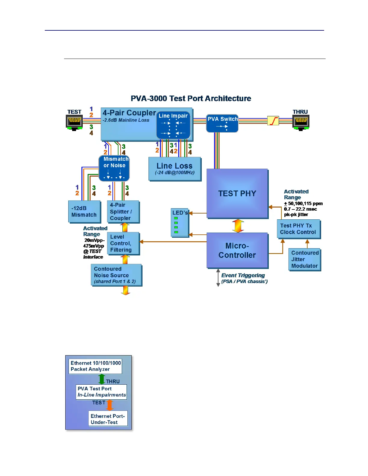
10/100/1000BaseT signaling that passes through the TEST interface will always
experience a 2.6dB power loss as it traverses a passive RF 4-Pair Coupler (see
Figure 2.1). This loss is frequency flat through 100MHz and is implemented with
100 matching impedance so as not to disturb any 100 terminations. It is
uniformly applied to each of the four LAN pairs.
The PVA Switch in Figure 2.1 then determines whether the TEST interface will be
terminated locally inside the test port or whether it will be transferred to the THRU
interface so that it can be connected to external instrumentation. The PVA Switch
is an electro-mechanical relay with DC to 1GHz frequency response. When the
TEST interface is connected to the THRU interface, all of the PVA test port
measurement capabilities become unavailable while certain impairments resources
remain fully available as “in-line” resources to external test equipment (see Figure
2.2).
Figure 2.2 PVA THRU Interface
Figure 2.1 PhyView Analyzer Test Port Architecture