PVA-3000 Reference Manual
December 2, 2019 Sifos Technologies
Each member of the PowerSync Analyzer family of instruments shares each of the following features:
Two, fully autonomous micro-controller hosted Test Ports per test blade or per instrument
One instrument controller per instrument
Instrument control over a single 10/100BaseT Ethernet interface
A USB (or older RS-232 Serial) interface exclusively for IP Address configuration and controller
firmware updates
PowerShell PSA: A Tcl/Tk based command console and script automation environment enabling
interactive command line configurations and queries as well as powerful features for automated test
development.
PVA Interactive Graphical User Interface: An instrument-specific software application for
interactive control and testing that sits on top of PowerShell PSA. PVA Interactive for the
PhyView Analyzer is a Tcl/Tk application that provides intuitive access to most PhyView Analyzer
testing resources.
Throughout this manual, the term PSA may be used to refer specifically to the PowerSync Analyzer family and more
specifically to the PSA-3000 chassis.
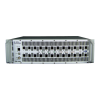
The PVA-3102 test blade has been engineered to work in all PowerSync Analyzer instrument chassis’. The following
table outlines configuration options and restrictions by chassis type.
Maximum Number of PhyView Analyzer Test Blades
PSA-3000 PowerSync Analyzer for PoE+
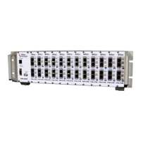
PSL-3000 Programmable Load for PoE+
PSA-1200 PowerSync Analyzer
6 (4 if combined with PSA-1200 test blades)
PSA-1200-PL Programmable Load
6 (4 if combined with PSA-1200-PL test blades)
1.2. Ethernet Twisted Pair PHY’s: A Brief History
Historically, Ethernet twisted pair physical layer (PHY) technology has evolved from simple bi-level digital pulse
signaling (e.g. 10BaseT) to more complex, higher density, wider bandwidth encoding schemes that depend upon
sophisticated digital processing technologies to both generate and recover digital traffic (e.g. 1000BaseT). The “Base”
terminology refers to the fact that Ethernet twisted pair PHY’s are baseband signals rather than modulated carriers that
are typically found in broadband network connections.
Under IEEE 802.3, strict rules regarding backward
compatibility and technology coexistence have assured smooth
and seamless transitions to newer and faster networking
technologies. The introduction of Auto-Negotiation with
100BaseTx enabled link partners to determine technology
compatibility so that links start up with the highest possible
performance level. Auto-Negotiation has since evolved to
resolve numerous link features between link partners.
On the cabling side, EIA/TIA Category 3 structured cabling
created the electrical conduit for 10BaseT. This was a low cost
transmission medium with capability to connect link partners up
to 100 meters apart. Category 3 cabling offered at least two
twisted pairs to support transmission in each direction. Primary RF characteristics included insertion loss (s21), return
loss (s11), and crosstalk. These parameters were verified out to 16MHz. 10BaseT’s transmission spectrum is tightly
spread around 10MHz given the Manchester coding of digital data.
Category 5 structured cabling generally included 4 pairs with parametric verification through 100MHz. This
performance enabled a 100BaseTx technology that was largely borrowed from FDDI (TP-PMD). The 100BaseT
coding scheme, MLT-3, spread the RF bandwidth of a transmitted signal well beyond 50 MHz, thus requiring the
added transmission bandwidth in order to support the 100 meter link length objective. Like 10BaseT, 100BaseTx only
required 2 pairs, one for transmission in either direction. This left two “spare pairs” in each cabling path.
While 100BaseTx extended both frequency spectra and information density, 1000BaseT took advantage of the four pair
cabling structure and then combined that with a duplex transmission scheme that simultaneously transmits signals in
both directions on the same twisted pair. Coupling that with higher density coding schemes, data bandwidth increased
an order of magnitude with very little spectral impact. On the cabling side, Category 5e was introduced to slightly
1990
1995
10BaseT
100BaseTx
1999
1000BaseT
10GBaseT
2006
E.E.E.
2010
PoE
2003
PoE+
2009
Cat 3
Cat 5
Cat 5e
Cat 6
TIA/EIA 568
IEEE 802.3
1990
1995
10BaseT
100BaseTx
1999
1000BaseT
10GBaseT
2006
E.E.E.
2010
PoE
2003
PoE+
2009
Cat 3
Cat 5
Cat 5e
Cat 6
TIA/EIA 568
IEEE 802.3
Figure 1.1 IEEE 802.3 & TIA/EIA 568 Timeline