PVA-3000 Reference Manual
December 2, 2019 Sifos Technologies
Ethernet ports can contribute to crosstalk in several
ways. Defective components and circuit trace
layout issues may lead to excessive crosstalk either
as a design feature or on an occasional port basis.
Many Ethernet ports utilize magnetics packages
that combine all 4 pairs into a single compact
package with tight spacing between coils.
Mechanical defects in sockets may also add to
crosstalk.
The PhyView Analyzer offers a calibrated
Crosstalk measurement that assesses near-end
crosstalk at the port-under-test interface. The
measurement reports crosstalk by pair
combination, that is, crosstalk between Pair #1 and
Pair #2 or between Pair #2 and Pair #4. (See
section 1.3.10 for discussion of pair numbering
convention.)
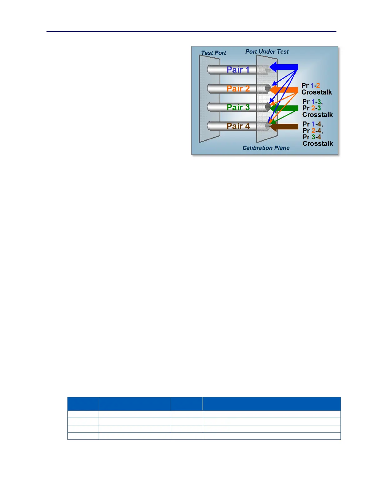
There are six unique pair combinations (see Figure 1.14):
The PVA Crosstalk measurement assumes that all crosstalk is bi-directional, that is, that crosstalk is really a
measurement of electrical isolation between two pairs. Well isolated pairs will report low crosstalk and poorly isolated
pairs will report higher crosstalk.
Much like the Return Loss measurement, Crosstalk is a wideband or bulk measurement across all frequencies, can only
be performed while linked at 1000BaseT, and is reported in dB. It is available only in 1000BaseT because that
technology was designed to enable signal power measurements that are correlated only to a specific transmission
direction on a specific pair.
Since there are no explicit limits from IEEE 802.3, hypothetical performance limits need to be discerned from other
specifications. In a 10/100BaseT channel, the only crosstalk that matters is Pair 2-3 since pairs 1 and 4 are not utilized
for data communication. In 1000BaseT, all four pairs are utilized in a full duplex fashion and any crosstalk that can be
measured on any pair will create an uncorrectable distortion at the receiving end of the link. If the link between two
ports were ideal, then the full budget of the NEXT formula limit line (see above) could be applied to the port-under-
test. Crosstalk would then range from –60dB at 1 MHz up to –27dB at 100MHz.
Given the spectral characteristics of a 1000BaseT transmission, the wideband equivalent to the NEXT formula limit
line approximates –37.8 dB. That is, the allowable crosstalk between any two pairs is about 0.017% of transmitted
power. The Crosstalk metrology is restricted to a floor of –39 dB and an error magnitude of 1 to 1.5 dB. This means
that the Crosstalk measurement is particularly useful for exposing design or manufacturing defects that cause
performance to degrade by worse than 3 to 6 dB relative to what the 802.3 standard hypothetically allows.
1.3.10. Pair Designators in the PhyView Analyzer
The PhyView Analyzer adheres to a pair numbering convention used in TIA/EIA-568-B. This convention is
commonly recognized throughout the cabling and connector industry. In this convention, pair numbers are related to
colors and RJ-45 connector pin numbers as follows:
Spare Pair for 10/100BaseT
MDI Transmit / MDI-X Receive Pair for 10/100BaseT
MDI-X Transmit / MDI Receive Pair for 10/100BaseT
Spare Pair for 10/100BaseT
Figure 1.14 PVA Crosstalk Measurement