PVA-3000 Reference Manual
December 2, 2019 Sifos Technologies
tracking threshold that is both magnitude and frequency dependent. A that point, performance of the receiver may
degrade very quickly.
In the absence of other impairments, most recent generation PHY technologies should tolerate well above the 1.4 nsec
pk-pk jitter levels specified in IEEE 802.3.
2.2.11. PVA Tx Level and Tx Slew Impairment
The TEST PHY also allows for configuration of output Tx Level and Tx Slew rate (or rise-fall time). These controls
can be used to complement the Line Loss impairment by either worsening or improving on the degree of impairment by
a small amount. They will also affect characteristics of test signals generated by the TEST PHY (see Section 2.2.1).
As was stated earlier in Section 2.1, the test port output level is normally attenuated by 2.6 dB because of the test port
4-pair coupler. This means that a “nominal” 2.0Vpp output signal would actually appear as 1.5Vpp. Since recent
generation PHY’s using digital signal processing must incorporate forms of automatic gain control, this slightly
reduced signal amplitude will have negligible effect on receiver performance and would represent the expected level of
low frequency insertion loss when the Line Loss impairment is connected.
The Tx Level control may be used to swing the output amplitude over a 2 dB range, that is ~ +1 dB. In absolute terms,
this would mean that the output level of a nominal 2Vpp signal could swing from ~1.35 to ~1.7Vpp.
The Tx Level is by default managed automatically by the TEST PHY and may be configured to automatic control at
any time. It offers 10 manual settings (1 to 10) that span the range described above. PSA Software will generally
manage Tx Level so that the output levels for 10BaseT, 100BaseTx, and 1000BaseT are exactly 2.6 dB below the
nominal level according to the respective 802.3 specification.
Tx Slew can be used to manipulate the rise and fall times of transmitted edges. Nominally, 100BaseTx specifies and
explicit 4 nsec (+1nsec) rise-fall time while 10BaseT and 1000BaseT define pulse masks that embed a range of possible
rise-fall times that vary from ~5 nsec (10BaseT) to ~3.6 nsec (1000BaseT). These numbers are made even less clear by
the fact that the different signal types have different amplitudes.
Within the PVA test port, Tx Slew may be varied so that a 100BaseTx signal can transition anywhere between 2.8 nsec
and 4.8 nsec (based on 0.8V transitions). The Tx Slew rate is by default managed automatically by the TEST PHY and
may be configured to automatic control at any time. When Tx Slew is reduced, i.e. longer rise-fall time, frequency
components in the transmitted signal above 70 to 75 MHz will be reduced and conversely, when Tx Slew is increased,
those same frequency components will be increased.
Like timing offset and jitter, these impairments are associated with TEST PHY configuration and operation and
therefore have no bearing on external instruments connected to the THRU interface.
2.2.12. PVA Rx Gain Control
One final topic related to test port and TEST PHY resources is the TEST PHY receiver gain control feature.
Generally, the TEST PHY like any modern PHY will manage its own receiver gain in order to optimize the recovery of
incoming signals. For this reason, there is not much
user benefit to manipulating receiver gain.
PhyView Analyzer meters (e.g. PSD, Echo) do need to
perform calibrations and measurements where receiver
gain is carefully controlled, so users should be aware
that “behind the scenes”, the TEST PHY receiver gain
is frequently configured and locked to a desirable
value. Whenever the TEST PHY is reset to it’s power-
on default state, Rx Gain will be automatic and will
remain in that state until meters need to lock it down in
a fixed state.
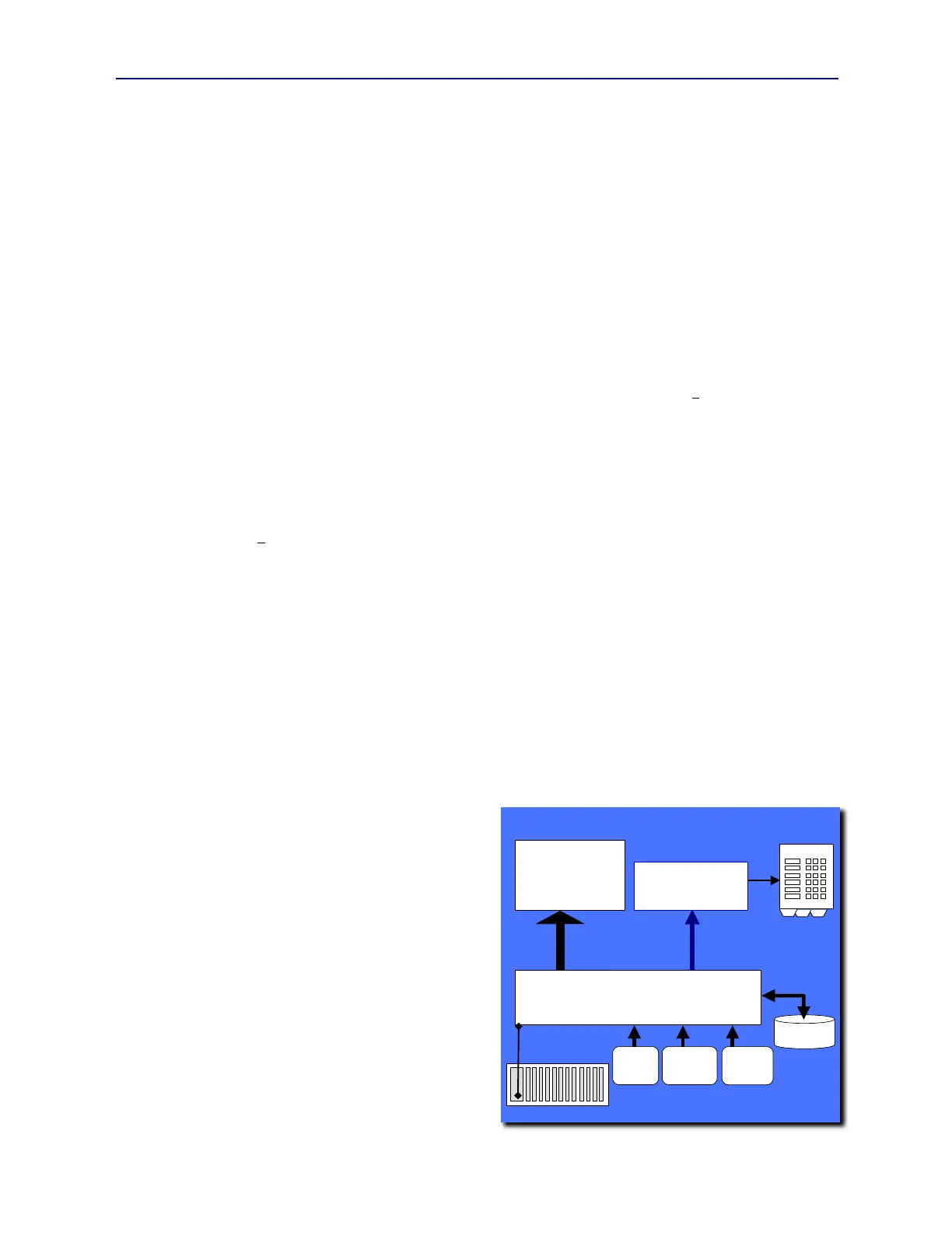
2.3. System Software Overview
The PhyView Analyzer requires externally hosted
software to operate. Because the PhyView Analyzer is
hosted on the PowerSync Analyzer (PSA) platform
(see Section 1.1.4), the host-based software will also be
referred to as “PSA Software” within this manual.
PhyView Analyzer software is primarily designed for
the Microsoft Windows operating environment. A
Figure 2.8 PVA Host Software Architecture
PVA Interactive
Graphical User
Interface Software
PowerShell PSA
TK/Tcl Based Application
Development Environment
10/100BaseT
Tk/Tcl
8.4.5+
API
Tk/Tcl
Libraries
PhyView Analyzer Software
Config
File(s)
Reports
PowerSync Analyzer
PHY Performance
Test Suite
Optional Feature
bwidget
Tk Library
PVA Interactive
Graphical User
Interface Software
PowerShell PSA
TK/Tcl Based Application
Development Environment
10/100BaseT
Tk/Tcl
8.4.5+
API
Tk/Tcl
Libraries
PhyView Analyzer Software
Config
File(s)
Reports
PowerSync Analyzer
PHY Performance
Test Suite
Optional Feature
bwidget
Tk Library