PVA-3000 Reference Manual
December 2, 2019 Sifos Technologies
When testing 100BaseTx receivers, the ability of the Link State to predict or estimate effective packet loss in a port-
under-test receiver is very much implementation dependent since the 100BaseTx standard is nebulous about the action
of receivers that are experiencing any degree of packet loss. Some PHY implementations may recognize error
conditions and attempt to force a re-link to overcome it. Any re-link can be detected as a link drop by the Link
Monitor.
In re-linking, some 100BaseTx PHY implementations may naturally drop back
to 10BaseT in an attempt to overcome serious channel impairments. The loss
thresholds at which any given PHY implementation makes decisions to drop
link and re-link is unspecified. Conversely, some PHY implementations, when
auto-negotiated to 100BaseT, will attempt to maintain 100BaseT link by
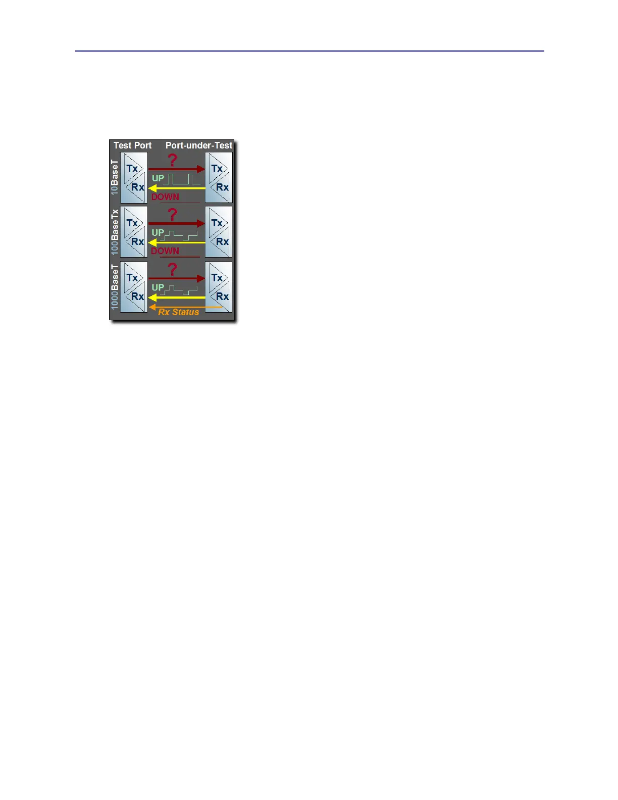
transmitting continuous IDLE MLT-3 signaling (see Figure 1.16) even when
incoming packet traffic and IDLE signaling is 100% impacted by bit errors.
Summarizing, for 100BaseTx, the relationship between Link Stability and
packet loss can range from very weak to very strong depending the PHY
implementation in the port-under-test.
1000BaseT introduced the concept of a receive status indicator combined with a
purely physical layer signaling protocol to communicate receiver status to the
link partner while linked (see Figure 1.16). Because of DSP processes
including forward error correction that are inherent in receiving 1000BaseT
signals, PHY implementations could more readily discern and communicate bit
error problems even when link performance was reasonably good. The Link
Monitor takes advantage of this feature in 1000BaseT by allowing Link State
(“UP” or “DOWN”) to be replaced by Remote Rx Status “OK” or “Not OK”.
Remote Rx Status can be sampled periodically from 1 to 100 samples at periodicity of 20, 50, or 100msec. Remote
Rx Status is a reasonably good predictor of bit error and packet loss performance.
The second option for receiver measurements in the PhyView analyzer is a simple Packet Flow measurement. This
involves the transmission of user-specified packets (size, gap, payload) into the port-under-test. The packets generated
by each PhyView Analyzer test port are restricted to MAC frames with programmable address, size, packet gap, and
repeating 4-byte payload. This technique therefore requires that the port-under-test must forward any successfully
received packets to another Ethernet port so that they may be returned to another PhyView Analyzer test port. Hence,
the device being tested must be a multi-port device with layer 2 bridging capability such as an Ethernet switch, hub, or
repeater.
The obvious advantage of packet flow testing is that it will always provide insight to the bit error performance of a
receiver regardless of link rate, that is 10BaseT, 100BaseTx, or 1000BaseT.
A disadvantage of Packet Flow is that it cannot be used on single-port devices or devices that don’t bridge layer 2
packet traffic. Another disadvantage is that it consumes two PhyView Analyzer test ports and is generally a bit more
complicated to configure and initialize than the Link Monitor. Often, layer 2 bridging must be “primed” in an Ethernet
switch as it executes spanning tree protocols in order to isolate connection paths. Finally, the PhyView Analyzer will
not filter received packets so that any rogue, unsolicited packets (e.g. LLDP or CDP) will add to received packet
counts, though usually at very low levels.
1.3.13. Receiver Testing with Impairments
A major contribution of the PhyView Analyzer toward 10/100/1000BaseT receiver testing is the ability to apply a
range of controlled and relevant impairments. Impairments are vital for moving the BER performance of any receiver-
under-test to a point where it can be measured much more quickly and can also be statistically compared to the BER
performance of other receivers.
Figure 1.17 diagrams this phenomenon and provides a quantitative perspective. For example, if the BER performance
of an unimpaired receiver is 10
-11
, that is one error in 10
11
bits, testing at 100BaseTx would yield a test time of over 13
minutes to discover the first packet error even when testing with the maximum packet size of 1518 octets. In
1000BaseT, this time is reduced by a factor of 10 and becomes just under 1½ minutes. Following up on the
relationships between packet errors and bit error rate (see Section 1.2.5), statistically, it takes many packet errors to
assess BER.
Impairing the receiver-under-test will drive up the BER, increase packet drops and packet error, and assess that receiver
under typical and worst case stresses.
Figure 1.16 Link Status Monitor