PVA-3000 Reference Manual
December 2, 2019 Sifos Technologies
The level of applied noise can be programmed at
the TEST interface from a minimum of –6 dB to
a maximum of +20 dB where 0 dB corresponds to
40mVpp, the 802.3 allowance for 100BaseTx
alien crosstalk noise. This noise amplitude range
equates to 20mVpp on the low end and 400mVpp
maximum. IEEE 802.3 specifies an allowance of
25mVpp, (= –4.0 dB) in 1000BaseT links and an
allowance of 300mVpp (= +17.5 dB) in 10BaseT
links.
Recent generation 10/100/1000BaseT PHY
implementations will typically tolerate
considerably greater noise ingress than 802.3
specifies, particularly in the absence of other
severe impairments such as Line Loss and Jitter.
The Alien Crosstalk impairment can also be physically disconnected from pairs 1+2 or pairs 3+4 by substituting the
Mismatch impairment. This means that noise can selectively be applied to the outgoing 10/100BaseT pair without
application to the incoming pair. It should also be noted that the level of noise applied at the TEST interface is reduced
by 2.6 dB as seen by the TEST PHY. This means the test port will force lower SNR levels on the port-under-test than
will be experienced by the TEST PHY.
As with the Line Loss and Mismatch impairments, the Alien Crosstalk impairment is available for in-line insertion
when devices on the THRU interface are routed through the TEST interface.
2.2.10. PVA Timing Offset and Random Jitter Impairment
When the TEST PHY is connected to the port-under-test, transmitted signal timing can be manipulated thus creating
another impairment to a receiver. Two modes of timing impairment are provided:
Fixed Frequency Offset
Edge Jitter
10/100/1000BaseT timing accuracy requirements are dependent on the link rate (see Section 1.2.1). Both 10BaseT and
1000BaseT expect bit timing to within +100 ppm of nominal frequency, that is, 10MHz for 10BaseT and 125
Msymbol/sec for 1000BaseT. 100BaseTx is more discerning with a specification of +50 ppm for a 125 Msymbol/sec
baud rate. The TEST PHY transmit frequency with zero offset
will be within 10 ppm of absolute nominal frequency.
TEST PHY transmit timing may be deliberately offset by any of
the following values: -115ppm, -100ppm, -50ppm, +50ppm,
+100ppm and +115ppm. These settings provide sufficient
range to push all receivers to the edge of their required
frequency locking ranges.
The PVA test port can also apply random modulated jitter onto
the transmit timing. In IEEE 802.3, both 100BaseTx and
1000BaseT standards specify a peak-peak jitter tolerance of 1.4
nsec to a receiver. Clause 40.6.1.2.5 further stipulates that the
jitter should have a phase noise profile where that portion of
peak-to-peak jitter above 5KHz should not exceed 300psec.
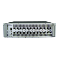
Each PVA test port includes a contoured jitter modulator (see
Figure 2.1) that will apply programmable random jitter to transmitted signal edges. The phase noise contour, as shown
in Figure 2.7, is designed to approximate the 1000BaseT jitter source requirement.
Jitter magnitude is expressed as dB where 0 dB equates to a 1.4 nsec pk-pk jitter level. Peak-to-peak jitter may be
programmed over the range of –6 dB to +18 dB which equates to 0.7 nsec to 11.1 nsec peak-to-peak.
Both Offset and Jitter are uniformly applied on all transmitted pairs when activated.
The effect of timing offset and jitter on any given 10/100/1000BaseT receiver is heavily dependent on the mechanisms
utilized in silicon-level PHY’s to acquire and lock to incoming receive signals. For this reason, jitter and offset may
have little or no effect on signal-to-noise ratio inside the PHY receiver until the magnitude of impairment exceeds some
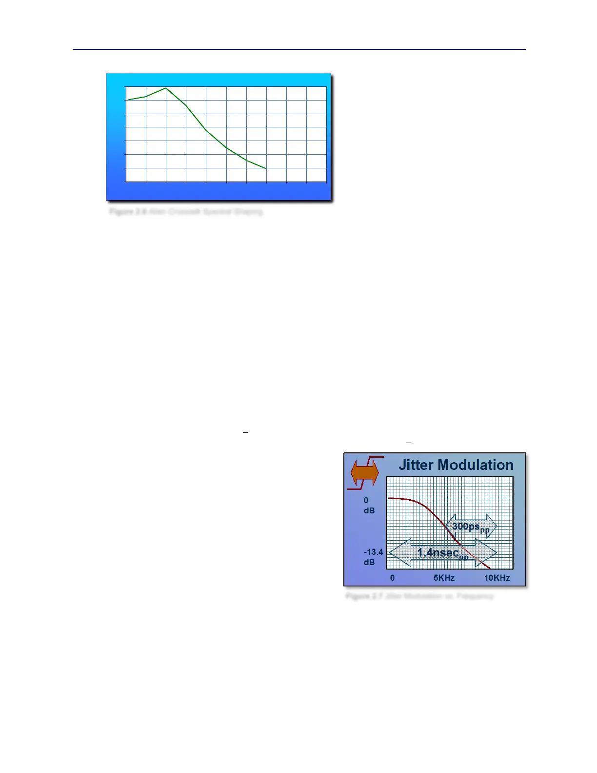
-30
-25
-20
-15
-10
-5
0
5
0 10 20 30 40 50 60 70 80 90 100
Figure 2.6 Alien Crosstalk Spectral Shaping
Figure 2.7 Jitter Modulation vs. Frequency