PVA-3000 Reference Manual
December 2, 2019 Sifos Technologies
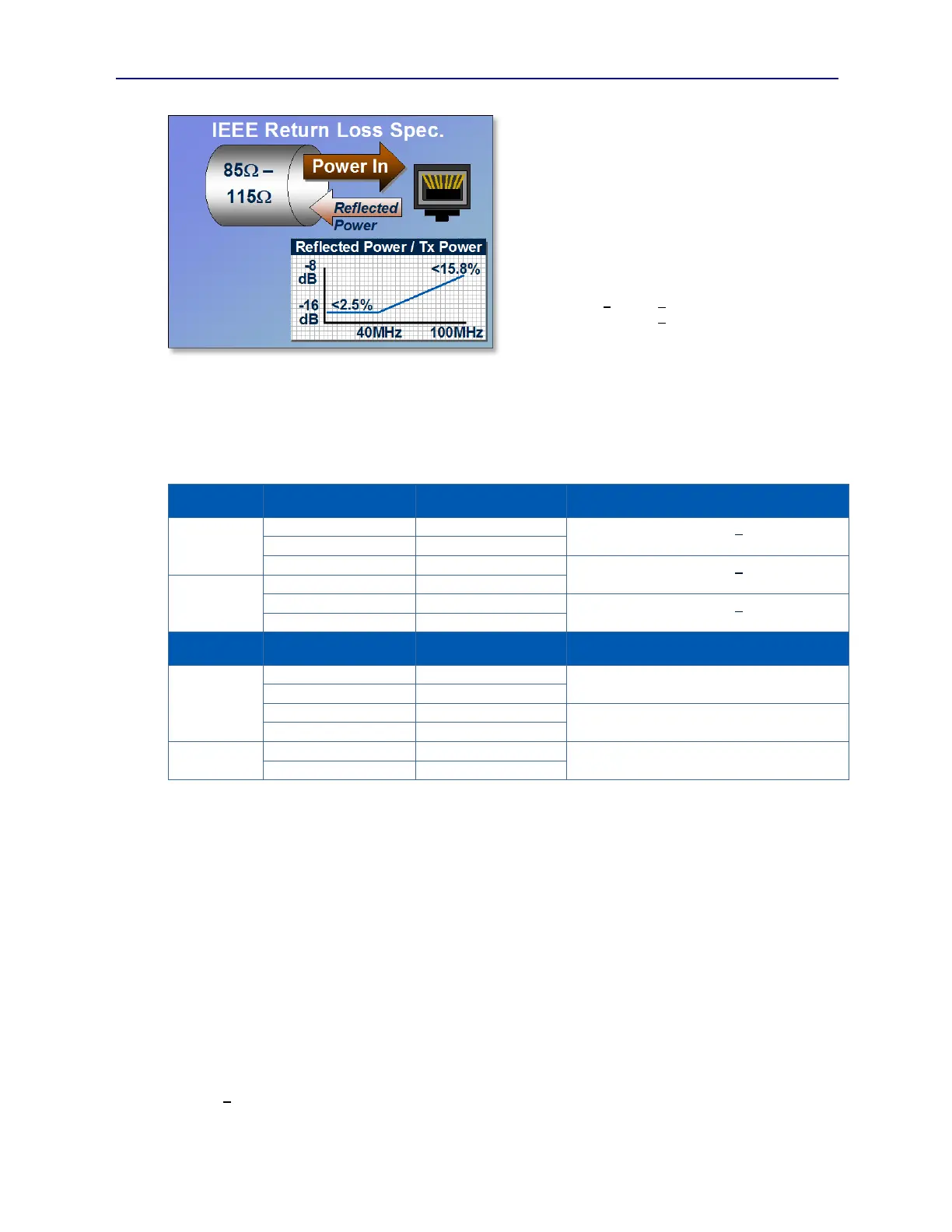
The IEEE 802.3 specification for Return Loss was
written with the constraint that Category 5 cabling may
have a characteristic impedance between 85 and 115
(see Figure 1.13). Normally, a return loss measurement
would be specified assuming a single, fixed channel
impedance such as 50. However in 802.3, it is
essentially specified with two reference impedances,
85 and 115. It is then expressed as a formula that
changes over frequency. The limit line formula from
802.3 clause 40.8.3.1 is:
Return Loss (<40MHz) < - 16 dB
Return Loss (>40MHz) < - (10–20*LOG(MHz / 80))
dB
To make this specification relevant to a test apparatus
that has fixed 100 impedance, some transformations are necessary. The following table shows what the port-under-
test must look like to a 100 source in order to meet the return loss requirements of -16dB (40MHz) and –8dB
(100MHz). It also computes a figure for –15.5 dB since, given the known 1000BaseT signal spectra (see Figure 1.6),
-15.5 dB approximately represents the wideband Echo power of a hypothetical port-under-test that tracks the 802.3
limit line function over frequencies from 1 to 100MHz.
Port Under Test
Impedance
83.5 to 117 will produce < -16 dB given a
reference anywhere between 85 and 115
49.5 to 197 will produce < -8 dB given a
reference anywhere between 85 and 115
82.1 to 119 will produce < -15.5 dB given a
reference anywhere between 85 and 115
Port Under Test
Impedance
100
Frequency
Selective
Frequency Range 0 – 40 MHz
Bulk Return Loss Limits that assure MDI Return
Loss specs across 85 to 115
Using this table, the wideband criteria for a compliant interface would be in the –20 to –21 dB Return Loss region.
The Return Loss metrology is restricted to a floor of –26 dB and an error magnitude of 1 to 1.5 dB. So a fair criteria to
apply to a typical port-under-test would be in the –19 to –20 dB range.
Bulk Return Loss is a calibrated measurement so that effects of cabling, connectors, and even test receivers are
properly compensated. Fully automated calibrations that require no external calibration standards simplify the task of
periodic calibration. Bulk Return Loss can be readily used to measure return loss across link components including
cabling, connectors, and patch panels.
1.3.9. Bulk Pair-Pair Crosstalk
Crosstalk is a ratio between the power transmitted on a single cable pair and the portion of that transmitted power that
leaks across into other cable pairs. It is generally thought of as a property of multi-pair cabling and connector
components. Typically, crosstalk increases with frequency owing to capacitive coupling between components.
IEEE 802.3 does not explicitly specify crosstalk performance of a 100/1000BaseT PHY, however it does specify the
use of TIA/EIA 568 (ISO/IEC 11801) qualified connectors that are in turn subject to various crosstalk specifications.
IEEE 802.3 also specifies expected near-end crosstalk (see Figure 1.14) performance of physical links that connect
Ethernet ports with the formula:
NEXT < 27.1 – 16.8*LOG( MHz / 100 ) dB
Figure 1.13 IEEE 802.3 Return Loss Specification