PVA-3000 Reference Manual
December 2, 2019 Sifos Technologies
earlier in Section 2.2.8 and diagrammed in Figure 2.1. No Impair fully removes this impairment from the test port.
Impair All applies it uniformly to all 4 pairs. Impair 1&2 and Impair 3&4 allow the Line Loss impairment to be
applied asymmetrically such that either Pairs 1 and 2 are impaired or Pairs 3 and 4 are impaired (see Section 1.3.10 for
discussion of pair numbering convention). The Line Loss impairment can be inserted in line with the TEST interface
regardless of the Port Connection selection.
The 12dB Mismatch impairment was also described in Section 2.2.8 and offers the exact same options as the 100
Meter Cat5e impairment whereby no pairs, two pairs, or all four pairs may be impaired at the TEST interface. The
12dB Mismatch connection to any pair can be used to inhibit the effects of any Random Noise impairment on that
pair.
Both the 100 Meter Cat5e and the 12dB Mismatch impairment selections will cause the Apply Selected Port
Settings (see Figure 3.11) button to annunciate the pending configuration change and are applied only when that button
is pressed and if the Port Impairments checkbox is selected with the Actions frame.
3.6.5. Active Impairments Sub-Menu
The Active Impairments consist of Random Noise (or Alien Crosstalk), Transmit Timing Offset, Transmit Jitter,
Transmit Level, and Transmit Slew.
The Random Noise impairment was discussed earlier in Section 2.2.9. Random Noise can be inserted on two or four
pairs at the TEST interface with an amplitude level that is in units of dB(40mVpp). This means that 0 dB corresponds
to 40mVpp, the 100BaseTx noise impairment allowance while –4dB corresponds to
25mVpp, the 1000BaseT noise impairment allowance.
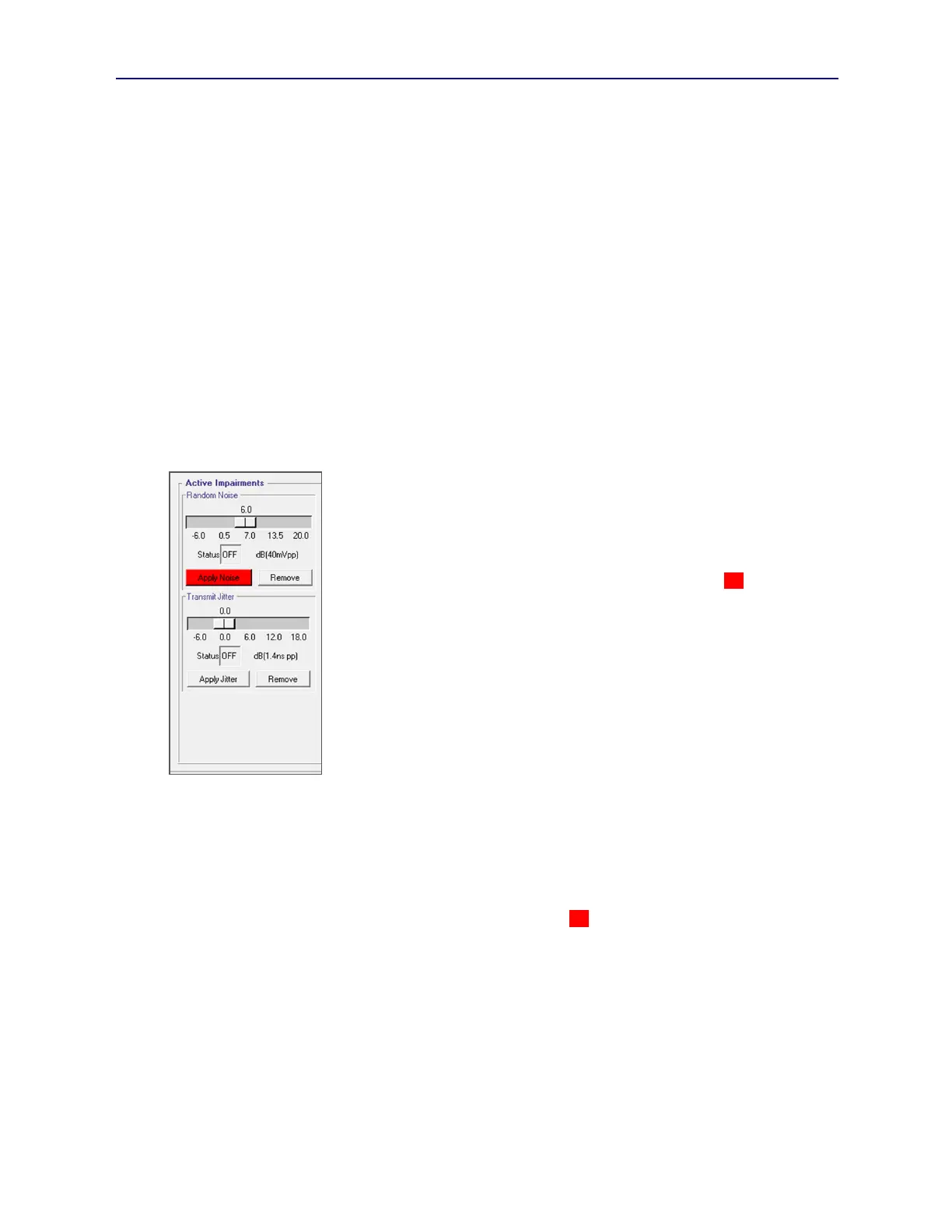
The Random Noise slider control (see Figure 3.12) allows noise level to be specified
from –6 dB to +20 dB in 0.5 dB increments. This corresponds to a range from 20mVpp
to 400mVpp at the TEST interface. (Note: Noise mVpp = 40*10
(Noise dB/20)
)
Moving the slider also causes the Apply Noise button to annunciate red (see Figure
3.12), an indication that the newly selected noise level will be applied when Apply
Noise is pressed. (Note: Active Impairment Apply operations are not in any way
governed by the Active Impairments checkbox in the Actions frame discussed earlier in
Section 3.6.2.) The Remove button in the Random Noise frame shuts off the noise
insertion at the TEST interface. As mentioned earlier, the 12dB Mismatch setting can
be used to inhibit noise impairment on two pairs by substituting the Mismatch
impairment on two pairs.
The actual status of the Random Noise impairment at the test port is shown in the Status
display. This will update whenever Apply Noise, Remove, or the Read Settings
buttons are pressed.
The remaining Active Impairments in the Port Config tab menu apply to all pairs and
are only meaningful when the TEST PHY is connected to the TEST interface. If
connected to the THRU interface, these controls are still fully available and will affect setup of the TEST PHY even
though that resource is not currently in use.
The Transmit Timing Offset impairment was described earlier in Section 2.2.10. Radio buttons allow selection of
transmit timing offset from nominal frequency, that is, 10MHz for a 10BaseT link, and 125MHz for a 100/1000BaseT
link. Options for timing offset are –50 ppm, +50 ppm, -100 ppm, +100 ppm, -115 ppm, +115 ppm, and No Offset.
Selecting any radio control will then cause Apply Offset to annunciate red, again meaning that the actual impairment,
or impairment removal, is only effected when Apply Offset is pressed.
Much like the Random Noise sub-menu, the Transmit Jitter sub-menu (see Figure 3.12) provides a slider control with
an Apply Jitter button and a Remove button. The Transmit Jitter impairment was also described in Section 2.2.10.
The slider allows selection of a jitter level between –6 dB and +18 dB where 0 dB corresponds to a peak-peak jitter
level of 1.4nsec, the IEEE 802.3 allowance level. When jitter level is adjusted, the Apply Jitter button will annunciate
the pending change and must be pressed to actuate it. Pressing Remove will shut off any transmit jitter.
Transmit Level and Transmit Slew impairments were described earlier in Section 2.2.11. The effective “off”
condition for these impairments is when each characteristic is controlled by the TEST PHY. This is achieved by
selecting Automatic. Alternatively, selecting Nominal will also mitigate any impairment effect of these transmit
signal characteristics by fixing them at a typical mid-range value.
Figure 3.12 Pending Apply