PVA-3000 Reference Manual
December 2, 2019 Sifos Technologies
Finally, It should be noted that PowerShell PSA is a more capable environment for running “sequences of sequences”,
for example, cueing up three PHY Performance Test Suite sequences to test three different DUT’s using one or more
PVA instruments to produce three separate Spreadsheet reports.
3.12.3. The DC Unbalance Analysis Application for PSE’s
A separate and distinct application within the PHY Performance Test Suite is the DC Unbalance Analyzer for Power
Sourcing Equipment (PSE’s). This test is specially formulated to analyze the impact of large DC currents coupled onto
Ethernet twisted pairs for the delivery of PoE (Power-over-Ethernet). The testing performed is therefore specific to
PSE’s and must be performed using two additional components:
1. A Sifos Technologies PSA-3000, PSA-3002, or PSL-3000 PoE analyzer
7. A Sifos Technologies PVA-DCU In-Line DC Unbalance Channel
The DC Unbalance Analyzer is explained further in Section 5.6.
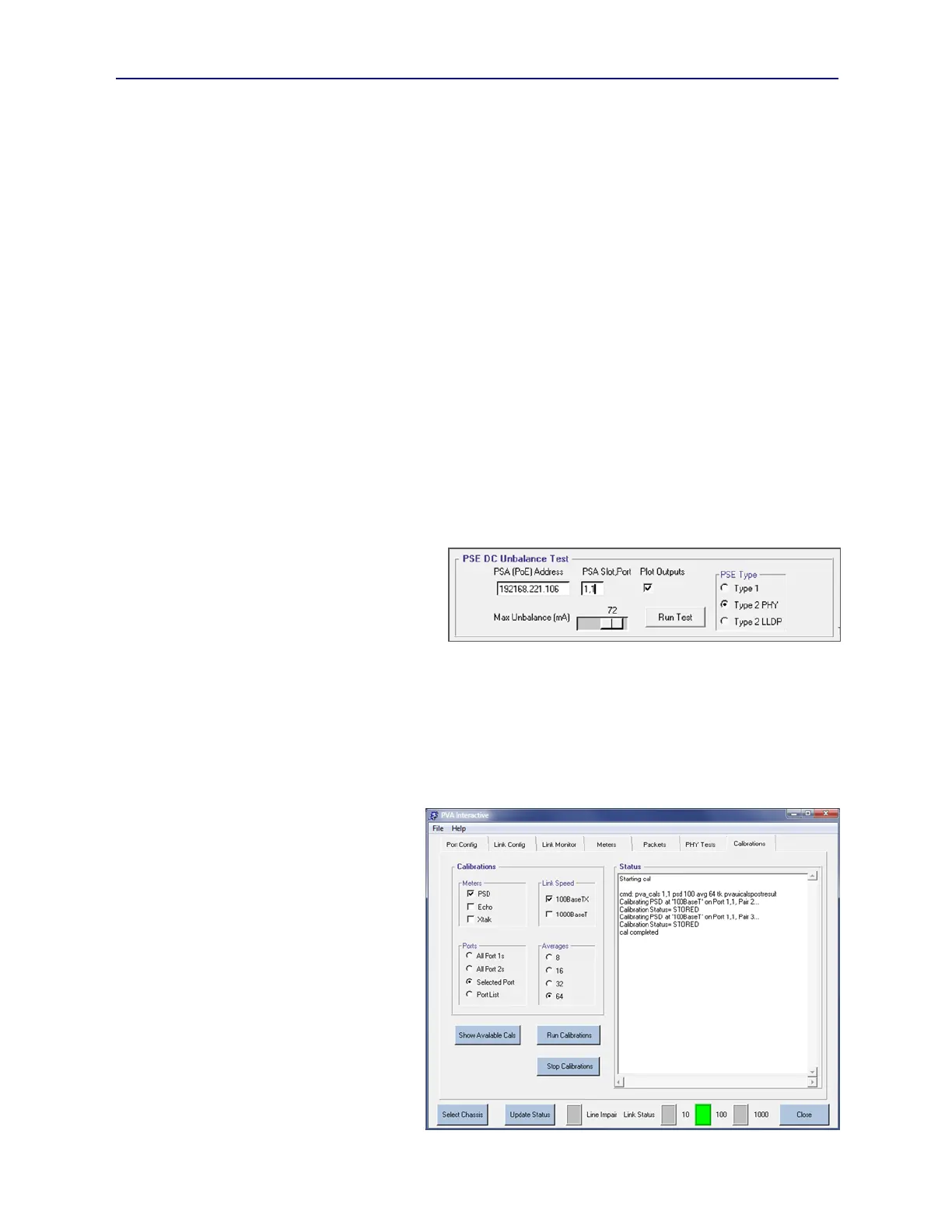
There are several configuration settings required before running the DC Unbalance Analyzer (see Figure 3.34):
PSA (PoE test blade) IP Address: This is the address of the PSA-3000, PSA-3002, or PSL-3000 that will be used for
powering up the PSE port and varying the degree of DC Unbalance load current. This address could be the same as the
current PVA instrument address if the test blades are co-located in the same chassis.
PSA Slot,Port: This is the PoE test port to be utilized during the analysis entered as in “slot,port” format.
PSE Type: This is the type of PSE according to the IEEE 802.3at standard. Type 1 is a 15.4 watt capable PSE,
Type 2 PHY is a 30 watt capable PSE that uses 2-event classification, and Type 2 LLDP is a 30 watt capable PSE that
uses LLDP for powered device classification. (Note: Type-2 LLDP specification will required that the PSA
instrument be enabled for the LLDP emulation feature.)
Max Unbalance (mA): This is the maximum
amount of DC Unbalance current that will be
created as the DC Unbalance Analyzer runs.
Measurements will be conducted at various
values of DC Unbalance Current (see Section
5.6) between a minimum of 30mA up to the
specified maximum value (80mA max.).
Plot Outputs: When checked, this option will cause the DC Unbalance Analyzer to automatically pop open a
spreadsheet report with graphical depictions of Low Frequency PSD and SNR versus DC Unbalance load.
Results of the DC Unbalance Analyzer will also be displayed in the Results display area.
3.13. Calibrations Menu
The final tab menu within the PVA Interactive tab menu is the Calibrations menu (see Figure 3.35). From this menu,
fully automated calibrations of PSD, Echo, and Xtalk meters are performed. The calibrations also include
verifications of PVA impairment
generators. All calibrations done from
this menu will automatically sequence
across pairs. Beyond that, calibrations can
sequence across Meters, Link Speeds, and
test Ports with the only restriction being
that only one test port per test blade (or per
PVA-3002 instrument) can be calibrated in
a single sequence.
The meter calibration process, including
test cables and physical hookups, was
described earlier in Section 2.2.6.
Calibration sequence configuration
involves selections for Meters, Link
Speed, test Ports, and Averages. Meter
options are PSD, Echo, and/or Xtalk.
Crosstalk (Xtalk) calibrations must be
preceded by Echo calibrations on each test
port, however both may be included in the
same sequence.
Figure 3.34 DC Unbalance Application for PSE’s
Figure 3.35 PVA Interactive Calibrations Menu