PVA-3000 Reference Manual
December 2, 2019 Sifos Technologies
Link Polarity, or connection mode, can be used to force an MDI or MDI-X connection locally at the TEST PHY
meaning that the DUT would be at the opposite connection polarity, MDI-X or MDI respectively. In 100BaseTx
testing, this configuration is essential to configuring which incoming pair has the transmitted signal, pair 2 or pair 3.
When configured to MDI, then pair 3 has the incoming signal, when configured to MDI-X, pair 2 has the incoming
DUT transmitted signal. Forcing the connection polarity also allows for receiver tests with asymmetric impairments
since only the outgoing transmit pair to the DUT need be impaired.
Setting Link Polarity to Automatic allows for the TEST PHY to link to any DUT whether it supports Auto-
MDI/MDI-X or not. The outcome will be random if the DUT does support Auto-MDI.
Like Link Speed and Link Duplex, configuring Link Polarity is a two-step process of Arm Configuration and RE-
LINK.
The Gigabit Config sub-menu allows users to specify whether the TEST PHY will operate in Master or Slave mode
following a 1000BaseT link-up. If the TEST PHY is in Master, the port-under-test will be forced to Slave and visa
versa. Certain physical layer measurements may be affected by whether the DUT is in Master or Slave mode while
receiver testing should generally be done with both modes. The Automatic configuration will allow auto-negotiation
protocol to determine whether TEST PHY and DUT end up as link Master or Slave.
Similar to the other link configurations described above, a change to Gigabit Config involves a two-step process of
Arm Configuration followed by RE-LINK. In this particular case, the Arm Configuration button is located in the
Gigabit Config frame.
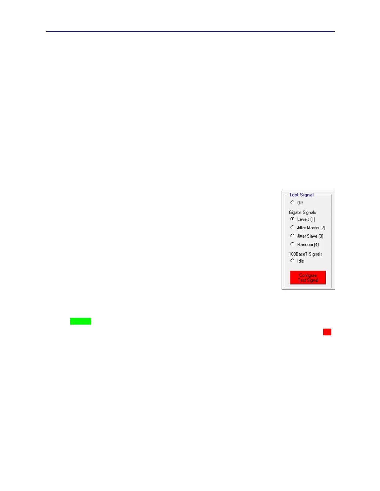
3.8.3. Test Signal Sub-Menu
Under the Test Signal sub-menu (see Figure 3.16), PhyView Analyzer test ports may be
configured to activate one of five test (transmitted) signals:
Gigabit Levels (1) (802.3 test signal #1 for pulse mask, all four pairs)
Gigabit Jitter Master (2) (802.3 test signal #2 for jitter, all four pairs)
Gigabit Jitter Slave (3) (802.3 test signal #3 for jitter, all four pairs)
Gigabit Random (4) 802.3 test signal #4 for distortion, all four pairs)
100BaseTx Idle (MLT-3 signal, pair #2)
These signals can be useful for evaluating TEST PHY transmit characteristics at the TEST
interface. For example, they will impacted by Transmit Level and Transmit Slew
configuration settings. Note that they are also impacted by the 4-pair RF Coupler loss
described earlier in Section 2.1.
When the Gigabit test signals are active, the TEST PHY will not be able to link. However,
the 100BaseTx Idle signal can cause a port-under-test to believe that it is linked and to transmit a 100BaseTx signals
and traffic. Note: PVA link status, as indicated both on the LINK LED and in PVA Interactive may indicate
“LINKED” while test signals are active.
When a test signal is selected or removed using the Off setting, the Configure Test Signal button will annunciate red
indicating the pending configuration change. Pressing Configure Test Signal will immediately cause the selected test
signal to activate (or de-activate given an Off configuration.)
3.8.4. Test PHY Sub-Menu
Generally, these settings should not be manipulated because TEST PHY receiver sensitivity is tightly controlled by
meters including PSD, Echo, Xtalk meaning that any configurations applied will be overridden when those
measurements are made. Since automated PHY tests use those meters, they too will override any settings applied in
this menu.
The Test PHY Sub-Menu allows for control of TEST PHY receiver gain/AGC characteristics. By default, the normal
Receiver Sensitivity setting is Automatic meaning the TEST PHY is in an automatic gain control state. When Reset
Test PHY is pressed, it will return the TEST PHY to this mode as will Apply Rx Level given the Automatic selection
in the sub-menu.
The Nominal Fixed setting for Receiver Sensitivity is the default setting used during calibrations and metering for
PSD, Bulk Return Loss (Echo), and Bulk Crosstalk. This setting is a low-to-mid scale gain level that will work for
incoming signals that traverse anywhere from 1 to 100 meters of Cat5 cabling. It corresponds to the Rx Gain setting of
“4” (on a 1 to 10 scale) that can be configured in PowerShell PSA. It is the only fixed gain (that is, non-automatic)
setting available for 10BaseT links.