PVA-3000 Reference Manual
December 2, 2019 Sifos Technologies
The Read Settings button updates configuration settings in the menu. This operation is more significant within the
Meters menu because each Meter Type maintains separate configuration settings meaning that the displayed
configuration settings may not reflect actual meter configuration after a Meter Type is changed. For example, if a
PSD measurement is configured and completed for 1000BaseT, Pair 2, 8 averages, then an SNR measurement is
configured and completed with 1000BaseT, Pair 1, 32 averages, when the PSD Meter Type is next selected, the prior
configuration of Pair 2 and 8 averages will only appear after pressing Read Settings.
The Copy Settings button, like the MEASURE button, will apply current configuration settings to the selected Meter
Type as displayed by the Sel. Meter label. It will then open the Port Replication menu described earlier in Section 3.7.
The only settings that will be copied to other test ports will be those settings associated with the currently selected
Meter Type.
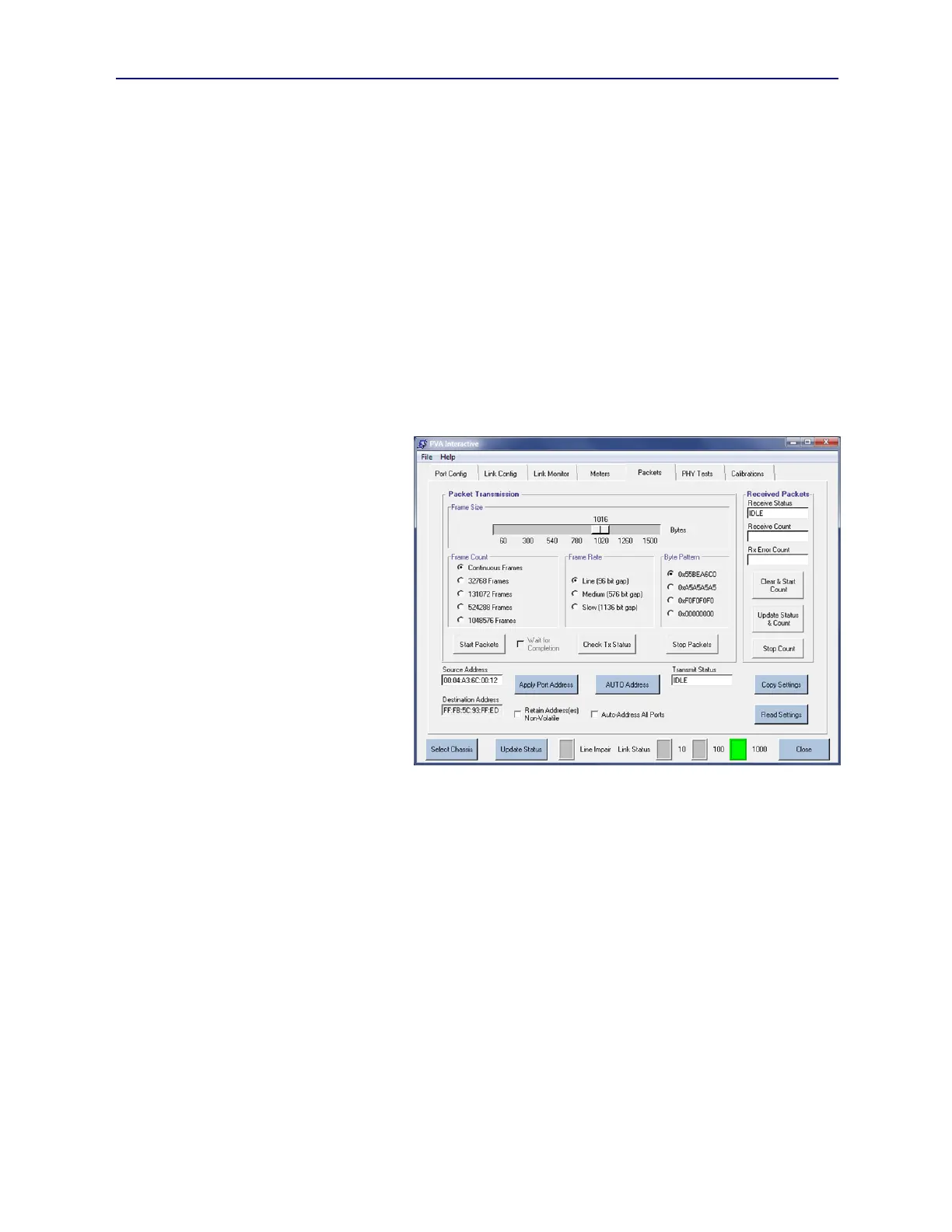
3.11. Packets Menu
As described previously in Sections 1.3.12 and 2.2.1, each PVA test port can synthesize, transmit, receive, and count
layer 2 (MAC) packets. PVA Interactive provides access to these capabilities in the Packets tab menu (see Figure
3.27). Packet transmission can be combined with any of the impairments described in earlier sections of this manual.
3.11.1. Configuring Packet Addresses
Each transmitted MAC frame includes a source address and a destination addresses. In the PhyView Analyzer test
port, the Source Address may be
configured whereupon the Destination
Address will automatically become the
binary inverse of that address. This
means that unicast source address (e.g.
00:…) will be paired with multicast
destination addresses (e.g. FF:….).
Generally, the best option for
configuring MAC addresses to support
packet flow testing is to allow PSA
software to automatically assign
addresses such that each test port has a
unique and valid unicast source address.
This is accomplished by selecting the
Auto-Address All Ports checkbox, then
pressing the AUTO Address button.
Furthermore, the addresses scheme
created can be stored in non-volatile
memory in each test port by selecting the
Retain Address(es) Non-Volatile
checkbox prior to pressing the AUTO
Address button. This sequence provides
the ultimate “set and forget” approach to packet flow addressing.
When AUTO Address is used, each port will have have a unicast source address starting with “00” and packets will
carry a layer 2 multicast destination address starting with “FF”. This should be noted when doing packet flow testing
concurrently between more than one port pair in a device-under-test such as an Ethernet switch.
Users may elect to manually enter a Source Address for each PVA test port by typing directly into the Source Address
field, then pressing the Apply Port Address button. This will then update both the Source Address and the
Destination Address according to the difference rule explained above. This address may be retained in non-volatile
memory if the Retain Address(es) Non-Volatile checkbox is selected prior to pressing the Apply Port Address
button.
3.11.2. Packet Transmission Configuration and Control
Transmitted packets from a test port will be of uniform size and content. Before a transmission is started, users have
control of packet size, burst size, packet gap (or rate) , and payload pattern.
Frame Size (or packet size) is selected using a slider control that ranges from a minimum packet size of 60 bytes to a
maximum size of 1512 bytes with size granularity of 4 bytes. The actual transmitted packets will then add 4 bytes for
CRC meaning the packet on the line for a 60 byte selection is 64 bytes total and for a 1512 byte selection is 1516 bytes.
There are five choices for Frame Count as follows:
Continuous: Transmit frames indefinitely until Stop Packets is pressed
Figure 3.27 Packets Tab Menu