PVA-3000 Reference Manual
December 2, 2019 Sifos Technologies
to time the link-ups.
Event Triggering requires that each meter have capability to operate as a simple state machine with four states as
diagrammed in Figure 2.3. When a measurement is initiated, the meter is placed in the ARMED state meaning that it
is waiting for the Event Trigger to actually begin the measurement. The configuration “timeout” parameter then
dictates how long the meter will wait for that trigger before giving up and returning to the READY state. Assuming
the trigger occurs within the configured timeout window, the meter will enter the MEASURING state. It will then
remain in this state until the actual measurement is completed, whereupon it will return to the READY state.
Triggered meters can be polled using status queries at any time as they move through the state machine. They always
will report current state, and if the measurement completes successfully, will report the measured result once they have
returned to the READY state.
2.2.6. PVA-3000 Meter Calibrations
Three of the PhyView Analyzer meters require local calibration on a periodic basis:
PSD
Echo Response
Crosstalk Response
Calibrations are designed to correct for effects of test ports and patch cables used in performing those measurements.
These calibrations are very analogous to the types of calibrations that might be
performed with classic RF network analysis where the effects of test cabling and
fixturing must be compensated in order to produce accurate insertion loss, return
loss, and isolation measurements.
IMPORTANT! In order for calibrations to be effective, patch cable test leads
should always be assigned to and associated with each test port. It is
recommended that the orientation of each test lead should also be maintained,
that is, the patch cable should have a test port plug and a device-under-test plug
side. Sifos Technologies provides high grade test cables with each PVA test port
and strongly recommends the exclusive use of these test cables.
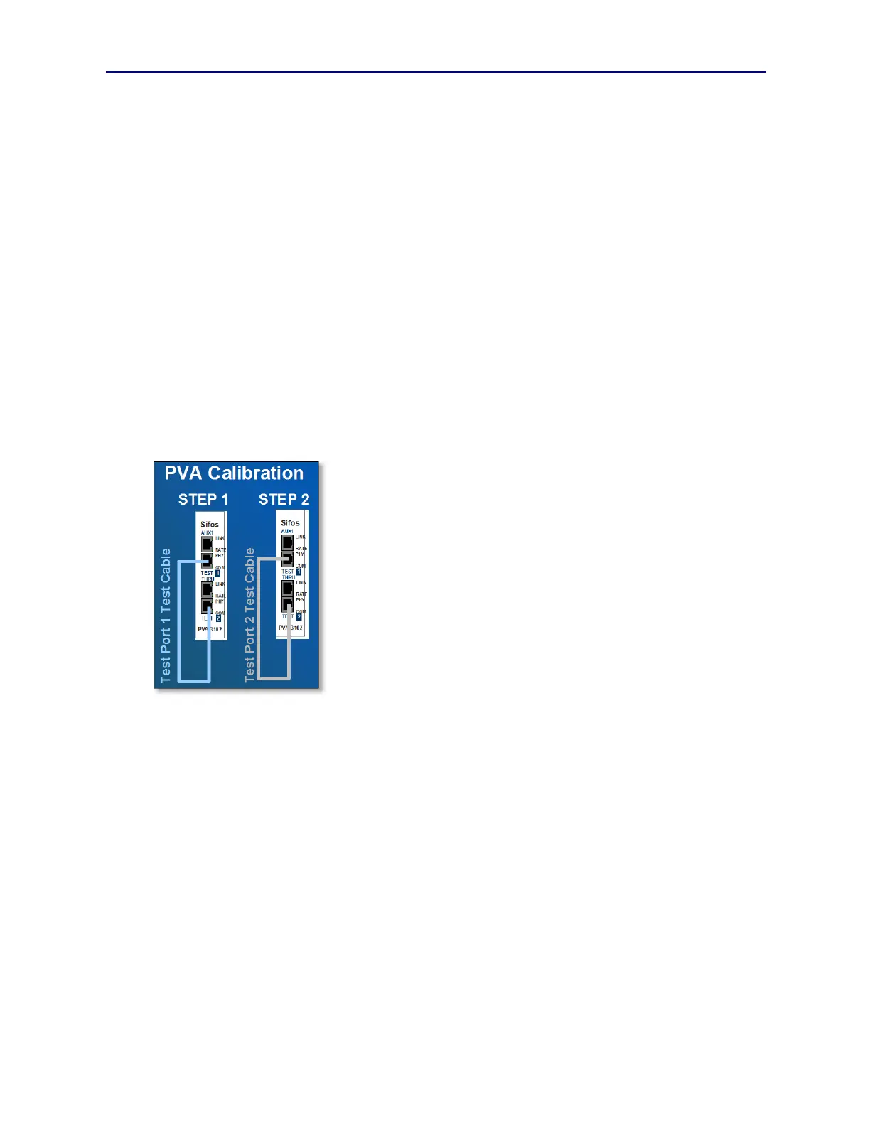
PVA-3000 calibrations are simple to execute. Each test port is considered to
have a “calibration partner” test port which by default is the other test port on the
same PVA-3102 test blade (or on the PVA-3002 instrument). So test port #2 is
the calibration partner for test port #1 and vice versa (see Figure 2.4). A
complete calibration of PSD, Echo, and Crosstalk is achievable simply by
connecting the patch cable associated with any test port to its calibration partner
port, then running automated calibration measurements (or sequences) from either
PVA Interactive software or PowerShell PSA software.
For any particular PVA-3000 configuration, calibrations will always require two distinct steps since only one test port
per test blade (or per PVA-3002) instrument can be calibrated at any one time. Automated calibration sequencing
allows even a fully populated PVA-3000 with 24 test ports to be calibrated in two steps.
Sifos Technologies does not offer any strict recommendations regarding calibration frequency. Instruments that are
parked in a laboratory and always mated to the same test cables should maintain calibration for weeks or months.
Instruments that are used very heavily with lots of test cable insertions should probably experience more frequent
calibrations as should any mobile instruments where test cables are routinely removed, then re-connected in different
settings.
PVA calibration data is collected and retained on the host computer. That means that when calibrations are completed,
they are only viable on the computer that executed the calibrations. Calibration files can readily be copied from one
computer to another should that be helpful in multi-host testing environments (see Section 2.3.5).
2.2.7. PVA-3000 Impairments - Overview
Section 1.3.13 reviewed the benefits of using physical layer impairments to improve defect coverage and testing
efficiency when testing receivers. Each PhyView Analyzer test port offers physical layer impairments as described in
the following table.
Figure 2.4 PVA Calibration Setup