ix
Copyright 2017 SolarCity Corporation. All rights reserved.
List of Figures
Figure 1-1: Typical PV installation with a SolarCity H6 inverter ............................................3
Figure 1-2: Block diagram of a complete SolarCity H6 inverter installation..........................4
Figure 1-3: Ratchet wrench, long-shank screwdriver, and chip puller................................. 7
Figure 2-1: SolarCity H6 safety labels .............................................................................. 14
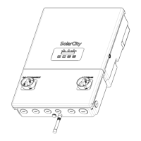
Figure 3-1: SolarCity H6 inverter with callouts ..................................................................17
Figure 3-2: SolarCity H6 inverter dimensions (front view) ................................................20
Figure 3-3: SolarCity H6 inverter dimensions (bottom view) .............................................20
Figure 3-4: Minimum clearances (below)......................................................................... 21
Figure 3-5: SolarCity H6 Inverter Mounting Bracket with hooks........................................22
Figure 3-6: Installing the Inverter Mounting Bracket on various wall types ........................23
Figure 3-7: DC Disconnect Switch in ON position ............................................................25
Figure 3-8: DC Disconnect Switch in OFF position ...........................................................25
Figure 3-9: AC Bypass Switch in the INV position.............................................................26
Figure 3-10: AC Bypass Switch in the BYP position ...........................................................26
Figure 3-11: SolarCity H6 inverter wiring box connections ................................................ 27
Figure 3-12: Wiring box label .......................................................................................... 27
Figure 3-13: Parallel string connections ..........................................................................29
Figure 3-14: Fireman Switch connections........................................................................30
Figure 3-15: Fireman Switch operation (below)................................................................30
Figure 3-16: DC Disconnect Switch operation (below) ......................................................30
Figure 3-17: High-voltage battery pack connections......................................................... 31
Figure 3-18: Communications connections (colors may vary)............................................32
Figure 3-19: Backup load connections.............................................................................33
Figure 3-20: AC grid POI output connections ..................................................................34
Figure 3-21: Mechanical Interlock Kit (MIK) Installed on a Main Panel ................................35
Figure 3-22: Mechanical Interlock Kit (MIK) Installed on a Manual Transfer Switch (MTS) ....36
Figure 3-23: RSS components and wiring ........................................................................43
Figure 4-1: Inverter orientation.......................................................................................49