118
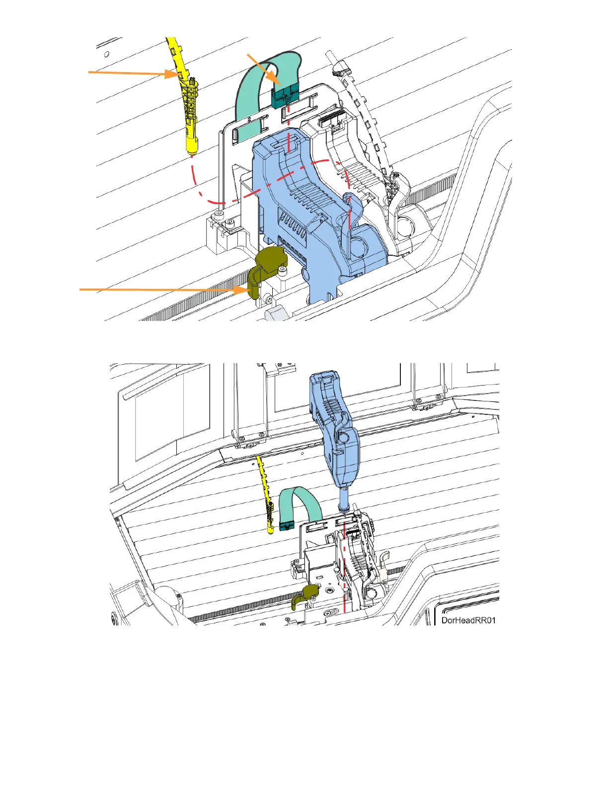
6. Pull the head assembly out of its position within the gantry and remove it from the printer.
Figure 5-12: Remove Head
7. Insert a new head assembly into the vacant location within the printer.
8. Lock the head into place using the head release lever. Press the lever securely closed to ensure
that the head is properly seated.
9. Connect the material tube to the new head assembly.
10. Insert the head ribbon cable connector into the new head assembly ensuring it is fully seated in
the head and the connector retention latch engages.
Head
Release
Material
Tube
Head Ribbon Cable