181
HEAD RIBBON CABLES
Required Tools
• 3 mm hex wrench
Removing the Head Ribbon Cables
1. With the printer powered ON, open the top cover.
2. Move the X bridge to the front of the gantry enclosure.
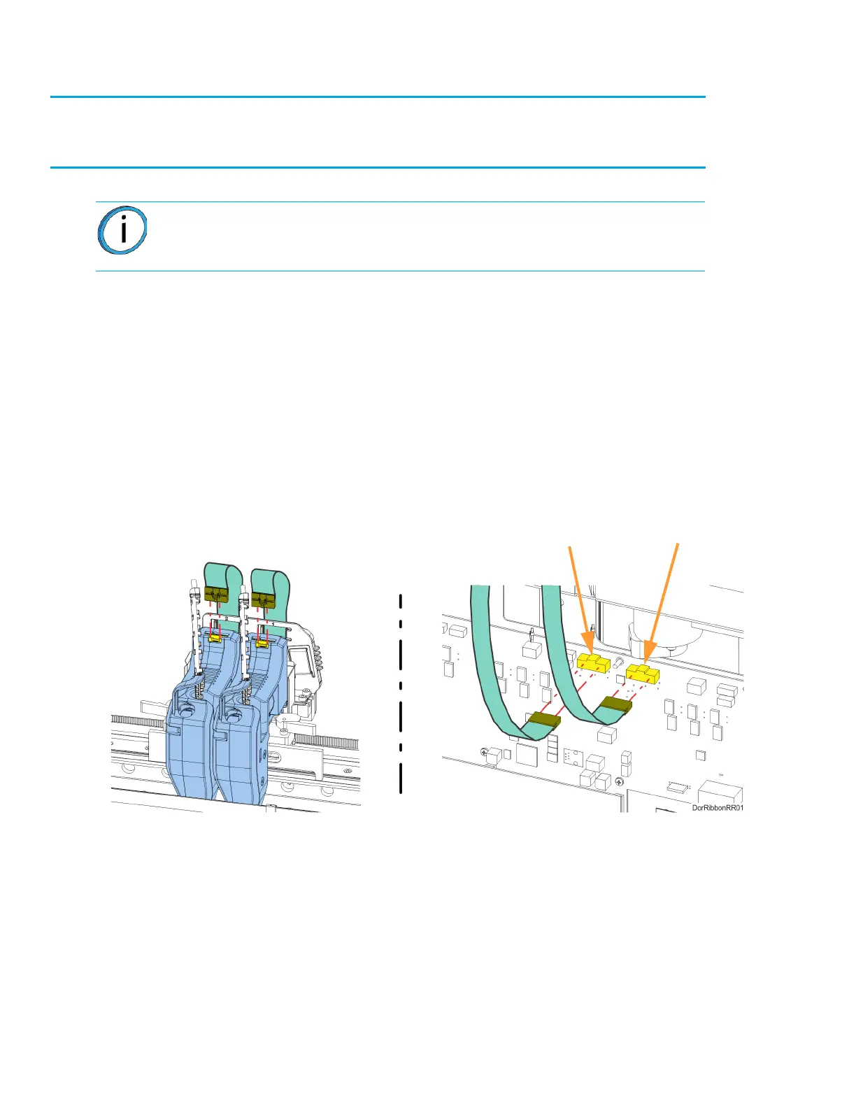
3. Disconnect the head ribbon cable connectors (2) from the tops of the material and support
heads. See Figure 7-22.
4. Power OFF the printer.
5. Remove the rear panel. See “Removing the Rear Panel” on page 170.
6. Disconnect the head ribbon cable connectors (2) from the I/O board (J6 and J7).
See Figure 7-22.
Figure 7-22: Head Ribbon Cable Connections
Note: Make sure to disconnect the head ribbon cables while the printer is
powered ON to ensure that auto-calibration occurs after re-installation.
Model Head J6
Support Head J7