The information contained in this document is confidential, and only for the information of the intended recipient and may not be published or redistributed without the prior written consent of Summa NV.
Summa nv Tel +32 59 27 00 11 Fax +32 59 27 00 63 Email support@summa.com Website www.summa.com Page 71 of 76
Make sure the loop of the media is correct. The basket should not cover the ultra-sonic
sensor.
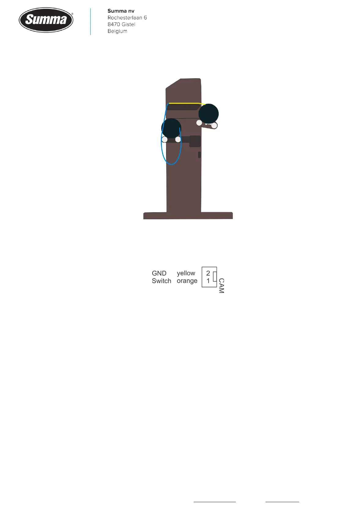
10.2.10 Cam switch
Currently there is no status information available. The Cam switch is wired to connector J15
on the main board.
Voltage can be measured with reference to the orange wire (pin 1): the yellow wire (pin 2) is
+5V when the pinch rollers are down on the drive drum. This causes the pinch roller switch
to open the contact, as this switch is wired to be closed when not activated. Lifting the pinch
rollers should result in 0V on the yellow wire (pin 2).
10.3 Worn X-motor detection
On the wider models (160, 140 and 120) there are two X-motors: one motor with encoder
and one motor without encoder. Both motors are driven equal by their own driver. Probably
one of the motors (or one of the drivers on the main board) is defective. To check if the
motor without encoder is still functional, a test can be conducted to measure the current
needed to feed the media (or to rotate the drive drum).
To access this “Monitor” screen, the machine needs to be started in “Service Mode”. Follow
the next steps:
1. Power on the cutter.