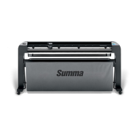
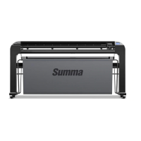
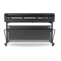
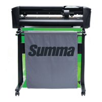
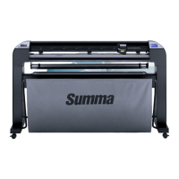
S CLASS™ cutter User’s Manual
Detailed Operation 4-9
4.3.1.4 OPOS
The OPOS settings are explained in detail in section 3, except for the Alignment mode,
monitor and OPOS paneling.
Alignment:
There are three additional alignment methods available on all S CLASS™ cutters:
X-Alignment, XY-Alignment and XY-Adjustment. These alignment methods can be used if
the combination of marker color – media color cannot be read by the OPOS sensor.
These alignment methods require that the user manually register markers using the cutter’s
keypad. Most cutting software can automatically put these markers around the printed
graphic.
X-Alignment compensates for errors in media alignment, by rotating the graphic’s contour.
This alignment method requires that the user specify the Origin and one point along the X-
Axis. X-Alignment is the simplest alignment method.
XY-Alignment compensates for errors in graphic rotation and skew. Skew errors occur when
the graphic’s X and Y Axes are not perpendicular. This alignment method requires that the
Origin and one point along both the X and Y Axes be specified.
XY-Adjustment compensates for errors in graphic rotation, skew, and scale. Scale errors
occur when the graphic’s printed size is different from the graphic’s original size as created
in the imaging software. X-Distance and Y-Distance parameters are required. These
parameters define the distance between the Origin and X-Axis point, and between the
Origin and Y-Axis point. XY-Adjustment is the most accurate manual alignment method.
Press the button, then use or to change the alignment method.
Press
to confirm or to cancel.
Default alignment method is OPOS.
OPOS paneling:
With this option, the markers can be read in panels. The OPOS sensor will read markers
according to panel size, instead off loading them all be.
OPOS Panels can be set to OFF or ON. When set to ON, then the sensor will load only 2
markers in X-direction when loading OPOS. Other markers will be read when unrolling
media. Must be used with internal or software paneling.
OPOS XY is not supported when using paneled OPOS.
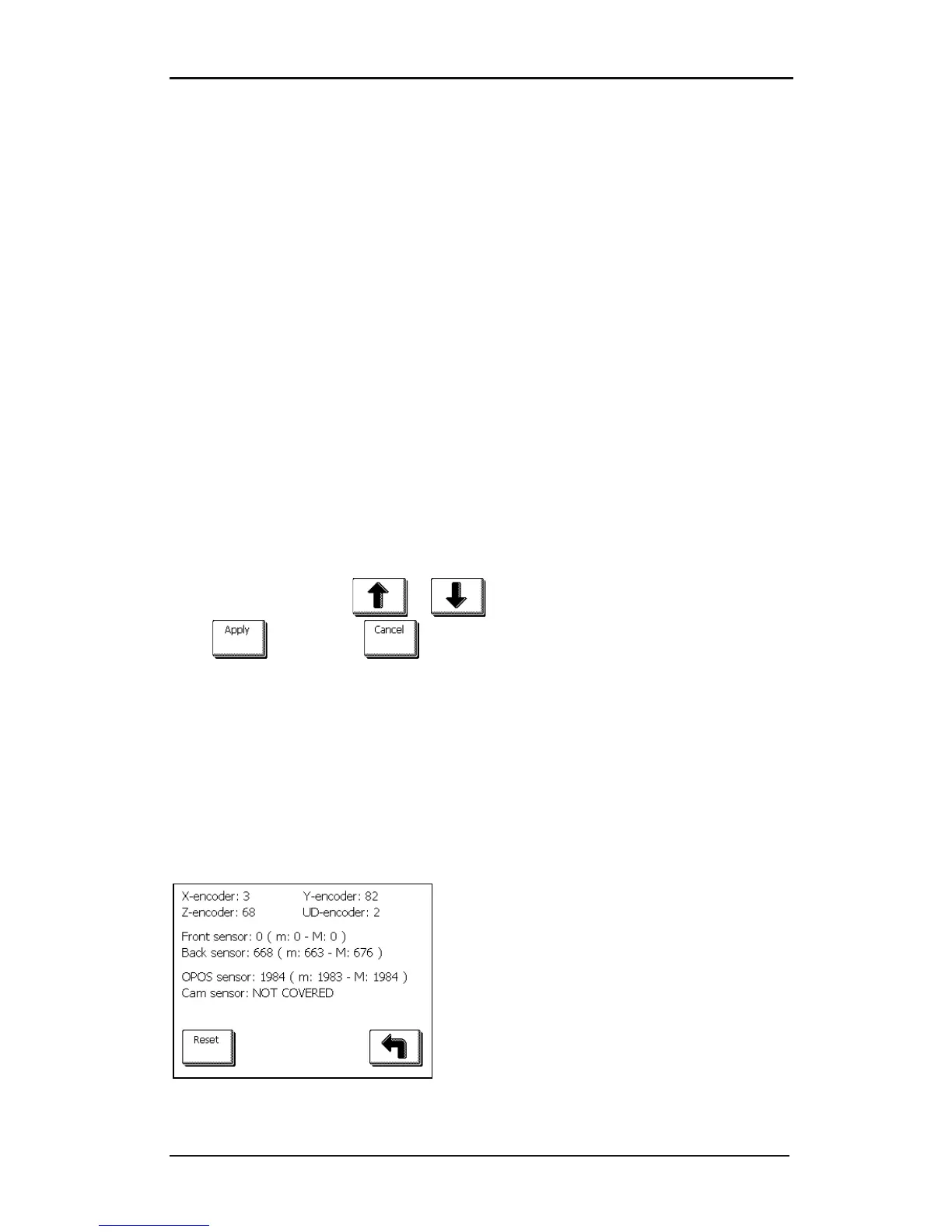
Monitor:
This option shows the read-out of all the sensors in
the cutter. X and Y encoder are for the position of
the X and Y motor. Z encoder is for the motor on a
T head. UD- encoder is the encoder inside the
head measuring the height. The front and back
sensors are the media sensors The OPOS sensor
shows the reflection of the OPOS sensor. Cam
sensor is the sensor to determine the position of
the pinch rollers. The values can be used to report
a problem to a certified service technician.