EasyManua.ls Logo

Svantek SVAN 971 - Page 146

Svantek SVAN 971
220 pages
Print Icon
To Next Page IconTo Next Page
To Previous Page IconTo Previous Page
Loading...
SVAN 971 User Manual Appendixes
146
Linear operating ranges for LEQ measurements with Diffuse Filter
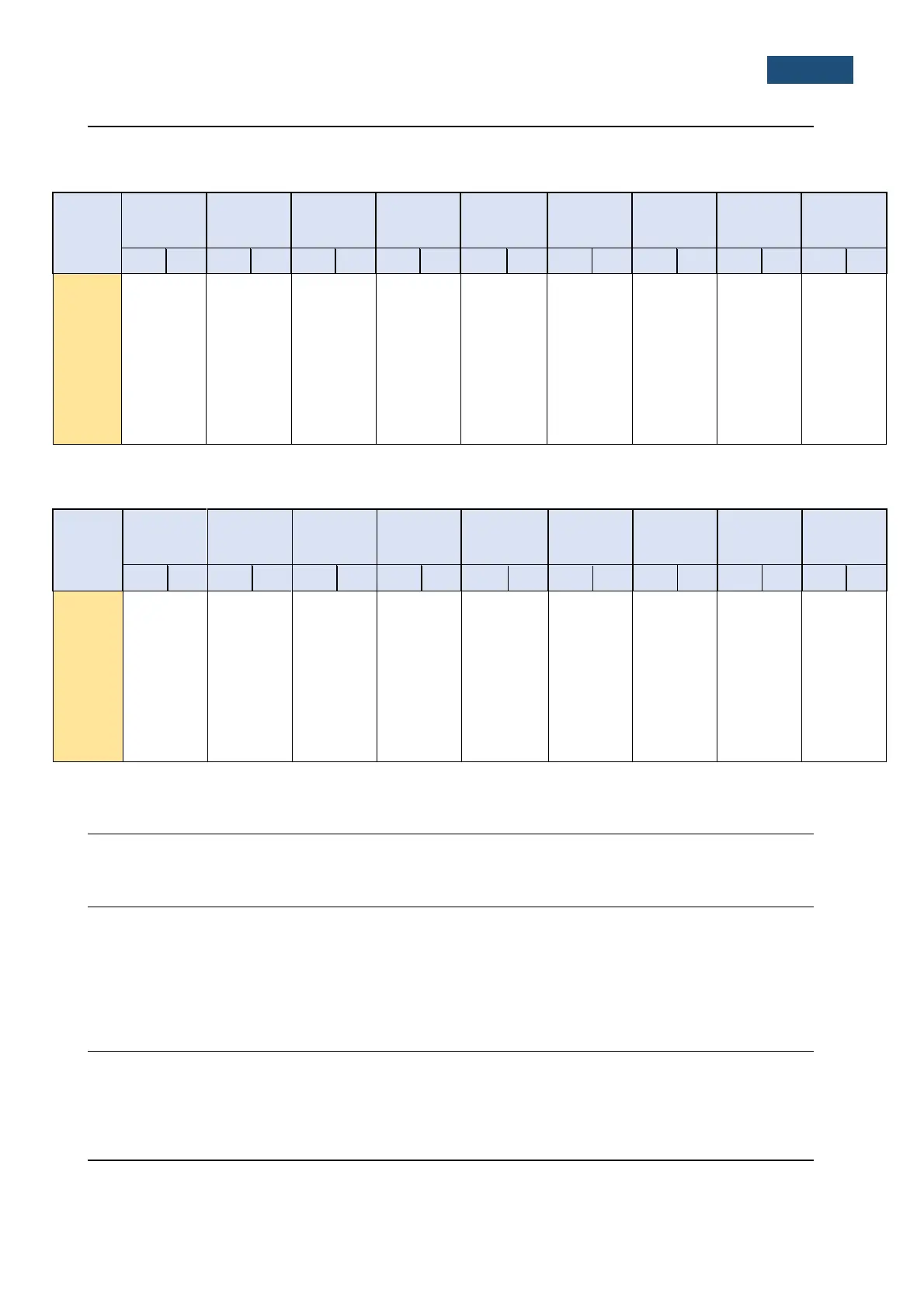
Table C.1.4. Linear operating range for the “Diffuse” filter: “LOW” for the sinusoidal signal and microphone
sensitivity 35 mV/Pa
[dB]
L
AS/F
L
BS/F
L
CS/F
L
ZS/F
L
AeqT
L
BeqT
L
CeqT
L
AE
L
Cpeak
(t
int
= 2 s)
from
to
from
to
from
to
from
to
from
to
from
to
from
to
from
to
from
to
31,5 Hz
26
83
26
106
26
120
32
123
26
83
26
106
26
120
29
86
50
123
500 Hz
26
119
26
122
26
123
32
123
26
119
26
122
26
123
29
122
50
126
1 kHz
26
123
26
123
26
123
32
123
26
123
26
123
26
123
29
126
50
126
4 kHz
26
124
26
122
26
122
32
123
26
124
26
122
26
122
29
127
50
126
8 kHz
26
122
26
120
26
120
32
123
26
122
26
120
26
120
29
126
50
123
12.5
kHz
26
118
26
117
26
117
32
123
26
118
26
117
26
117
29
121
50
120
Table C.1.5. Linear operating range for the “Diffuse” filter: „HIGH“ (primary level range) for the sinusoidal
signal and microphone sensitivity 35 mV/Pa
[dB]
L
AS/F
L
BS/F
L
CS/F
L
ZS/F
L
AeqT
L
BeqT
L
CeqT
L
AE
L
Cpeak
(t
int
= 2 s)
from
to
from
to
from
to
from
to
from
to
from
to
from
to
from
to
from
to
31,5 Hz
36
97
36
120
36
134
42
137
36
97
36
120
36
134
39
100
60
137
500 Hz
36
133
36
136
36
137
42
137
36
133
36
136
36
137
39
136
60
140
1 kHz
36
137
36
137
36
137
42
137
36
137
36
137
36
137
39
140
60
140
4 kHz
36
138
36
136
36
136
42
137
36
138
36
136
36
136
39
141
60
139
8 kHz
36
136
36
134
36
134
42
137
36
136
36
134
36
134
39
139
60
137
12.5
kHz
36
132
36
131
36
131
42
137
36
132
36
131
36
131
39
136
60
134
Linear operating ranges with the SA 22 windscreen
See C1.2
RMS detector
Digital “True RMS“ with Peak detection,
Resolution 0.1 dB
Range 327.7 dB
Crest Factor unlimited (for signals in 20 kHz band).
Overload detector
The instrument has the built-in overload detectors. The overload in the measurement channel (in its analogue
part) and the overload of the analogue / digital converter are both detected. The “overload” indication is when
the input signal amplitude is 0.5 dB above the declared “Peak measurement range
Underrange detector
The instrument has the built-in underrange detector. The “underrange” indication appears when the minimum
value of the RMS detector output goes below the specified lower linear operating range

Table of Contents

Related product manuals