Time of signal recording
The Rec. Time parameter defines the time of signal recording after triggering. If
next trigger condition appears during the Recording Time, the signal will be
recorded for additional Rec. Time. The available values are from 1s to 8h, or
infinitive (Inf).
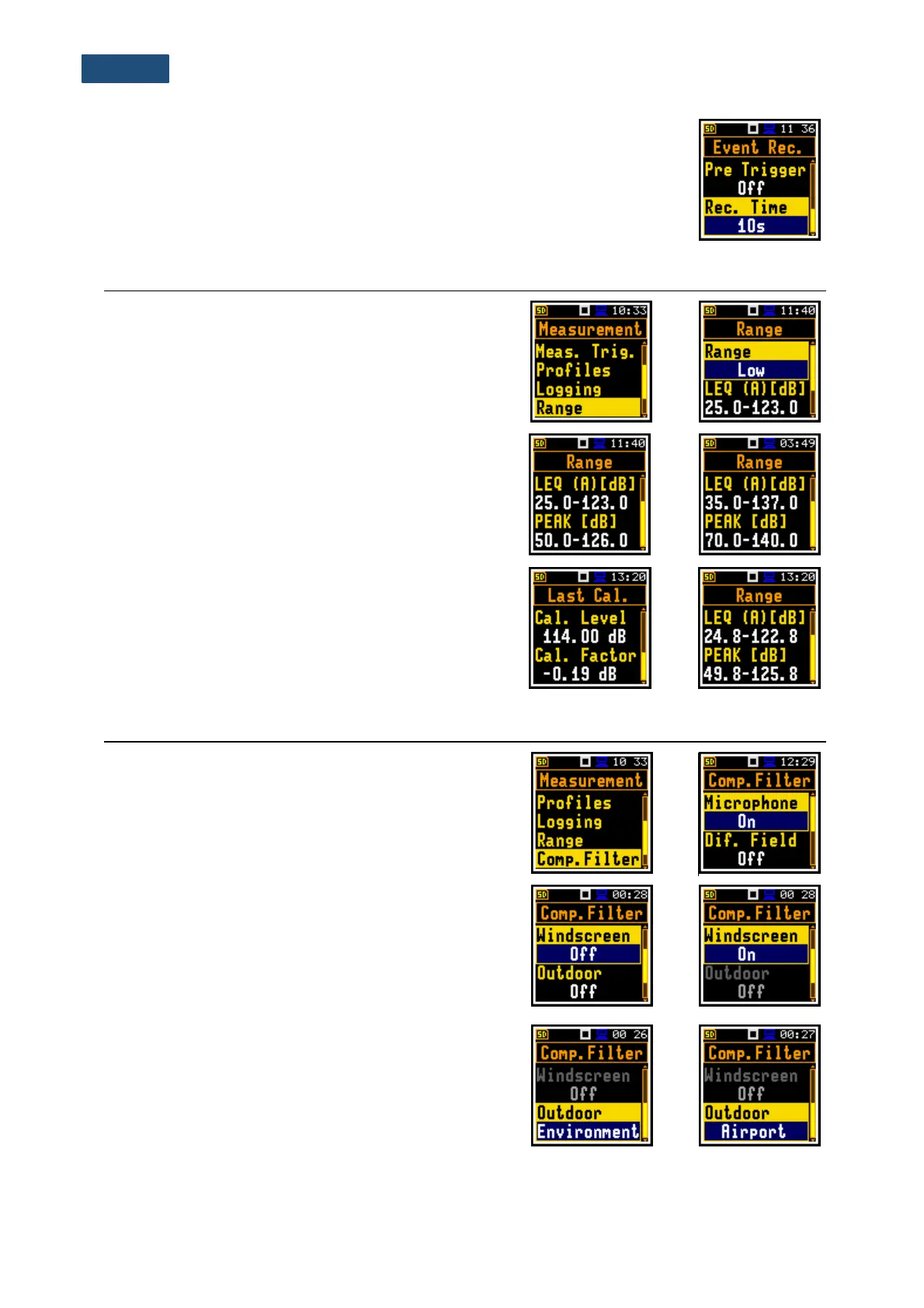
5.6 MEASUREMENT RANGE SELECTION – RANGE
The Range position is used for setting one of the
available measurement ranges in the instrument.
The absolute range values depend on the calibration
factor and are shown on the Range screen.
There are two ranges available: Low and High. The
detailed description of the measurement ranges
parameters is given in Appendix C.
The above screens were made with calibration factor
equal to zero. The calibration factor is always added to
the upper range level – see example.
5.7 SWITCHING ON THE MICROPHONE COMPENSATION – COMPENSATION FILTER
The Comp. Filter position is available only in the
Advanced interface mode.
The Microphone filter (microphone inner noise
compensation) is switched on by default, however it is
possible to switch it off for electrical measurements (e.g.
for laboratory calibration measurements).
The Dif. Field filter enables you to set compensation for
sound measurements in the diffuse field conditions. The
microphone supplied with SVAN 971 (ACO 4052 –
38 mV/Pa, prepolarised ½” condenser microphone) is
designed for sound measurements in free field
conditions. The Windscreen position switches on the
compensation when windscreen is applied.
The Outdoor filters are dedicated for the permanent
outdoor monitoring application as a part of the SV 271
monitoring station. The characteristics of the outdoor
filters depend on the application: Environment (the
acoustic signal is parallel to the microphone’s grid) or
Airport (the acoustic signal is perpendicular to the
microphone’s grid). The frequency characteristics of the
designed filters are given in Appendix D.