Physical Description 29
ID: um_t2gateway CP560 DVB-T2 Gateway User’s Manual Rev. 2.2 (3686)
6 Physical Description
6.1 Connecting the CP560
6.1.1 Physical description overview
The front panel provides two LEDs per CP560. The meaning of each LED indicator is shown
in table 6.1.
Table 6.1 Front panel LED descriptions
Indicator Colour Description
Power Green This LED is lit when power is on and initialization is complete
Alarm Red This LED is lit when a failure is detected by the unit
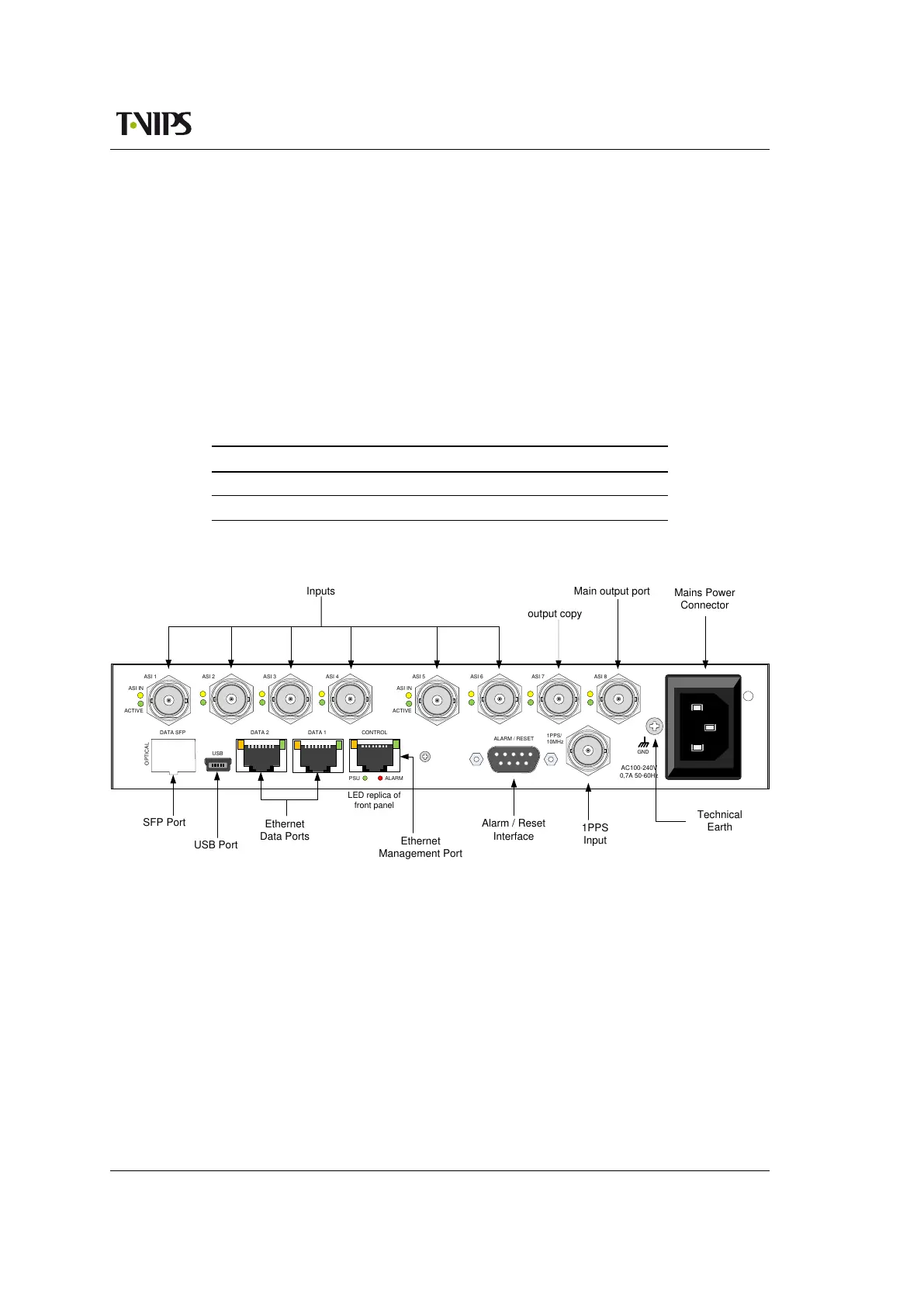
These LEDs are also replicated on the rear panel, which is shown in figure 6.1.
Inputs
GND
OPTICAL
USB
1PPS/
10MHz
ALARMPSU
ALARM / RESET
CONTROL
AC100-240V
0,7A 50-60Hz
ASI IN
ACTIVE
ASI 1 ASI 2 ASI 3 ASI 4
ASI IN
ACTIVE
ASI 5 ASI 6 ASI 7 ASI 8
DATA 2DATA SFP DATA 1
USB
Main output port
SFP Port
USB Port
Ethernet
Data Ports
Alarm / Reset
Interface
1PPS
Input
Mains Power
Connector
Technical
Earth
output copy
Ethernet
Management Port
LED replica of
front panel
Figure 6.1 Rear panel on 2 ASI card variant
Remove mains supply before moving or installing the equipment. Ensure ESD precautions are
observed while interconnecting equipment.
6.1.2 ASI ports
The CP560 can be shipped with one ASI card with 10 ASI connectors as shown in 6.2. Another
configuration includes 8 ASI connectors on the back panel as shown in figure 6.1.
When the CP560 is used with ASI output, one port is reserved for the single supported TS out-
put. A number of the ports are reserved for input, while the remaining ones can be configured
either as inputs or copies of the main ASI output port. Switching of the direction on a port
does not require a re-boot, and can be performed while the other ports are in service.