30 Physical Description
CP560 DVB-T2 Gateway User’s Manual Rev. 2.2 (3686) ID: um_t2gateway
The available options for each port are shown in table 6.2 for the 2 ASI card and 1 ASI card
configuration.(X) means valid option, (-) means not valid.
Table 6.3 Port direction options on
the 10 connector variant
ASI port Input Output Copy Output
1 X X -
2 X X -
3 X X -
4 X X -
5 X X -
6 X X -
7 X - -
8 X - -
9 - X -
10 - - X
GND
OPTICAL
USB
1PPS/
10MHz
ALARMPSU
ALARM / RESET
CONTROL
AC100-240V
0,7A 50-60Hz
DATA 2DATA SFP DATA 1
USB
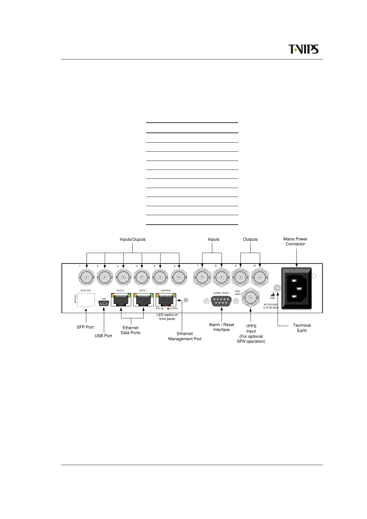
Inputs/Ouputs
Mains Power
Connector
Technical
Earth
1PPS
Input
(For optional
SFN operation)
Alarm / Reset
Interface
LED replica of
front panel
Ethernet
Management Port
Ethernet
Data Ports
USB Port
SFP Port
1
2
3
4
5 6
7 8 9 10
Inputs
Outputs
Figure 6.2 Rear panel with 10 ASI connectors
6.1.3 ASI input ports
All physical input ports can be available for usage, but the number of simultaneously enabled
ports is limited by the licence key Number of ASI ports activated.
In the eight ports configuration, each ASI input port has two LEDs associated with it. The
yellow LED indicates active input and the green LED indicates that sync is detected.