AGL7 module adjustment procedures
Procedure
WARNING. To avoid serious injury, do n ot touch exposed connectors or
components when operating the TG8000 mainframe with the top cover removed.
Dangerous potentials exist at several points within the TG8000 mainframe.
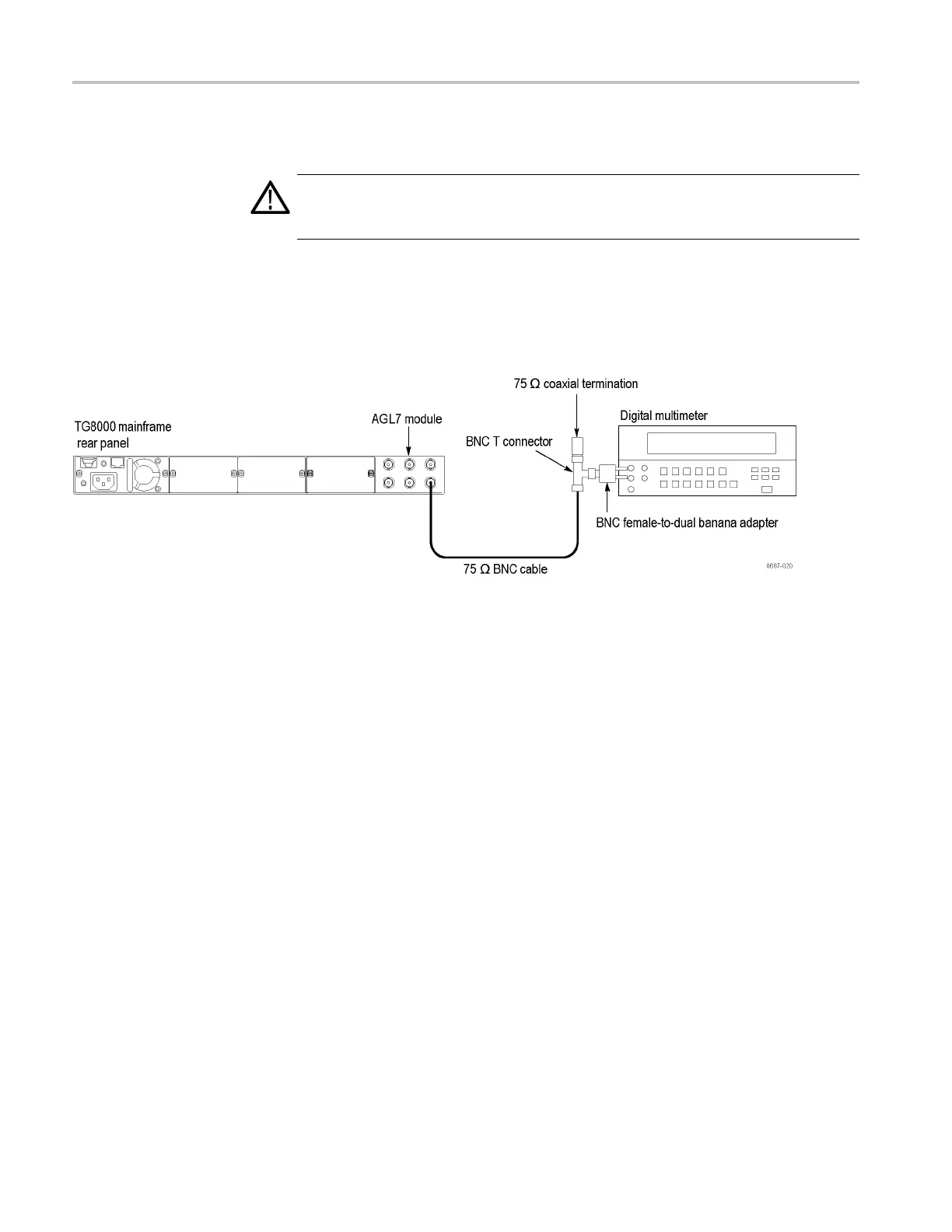
1. Use the 75 Ω BNC cable, B NC T connector, 75 Ω coaxial terminator, and
BNC female-to-dual banana adapter to connect the BLACK 1 connector on
the AGL7 Genlock module to the I NPUT connector on the digital multimeter
as shown. (See Figure 4-2.)
Figure 4-2: Equipment connection for adjusting the output offset and gain
2. Restart the instrument in Factory mode:
a. Press
andholdtheMODULE, ENTER,andFront Panel ENABLE
buttons simultaneously.
b. Cont
inue holding the buttons until the message TG8000 Booting...
displays.
c. Whe
n the message TG8000 Booting... displays, release the MODULE
and ENTER buttons. Continue holding the Front Panel ENABLE
button.
d. When the message TG8000 Start up with Factory Mode displays,
release the Front Panel ENABLE button.
4–4 TG8000 Multiformat Test Signal Generator Service Manual

 Loading...


