AVG7 module adjustment procedures
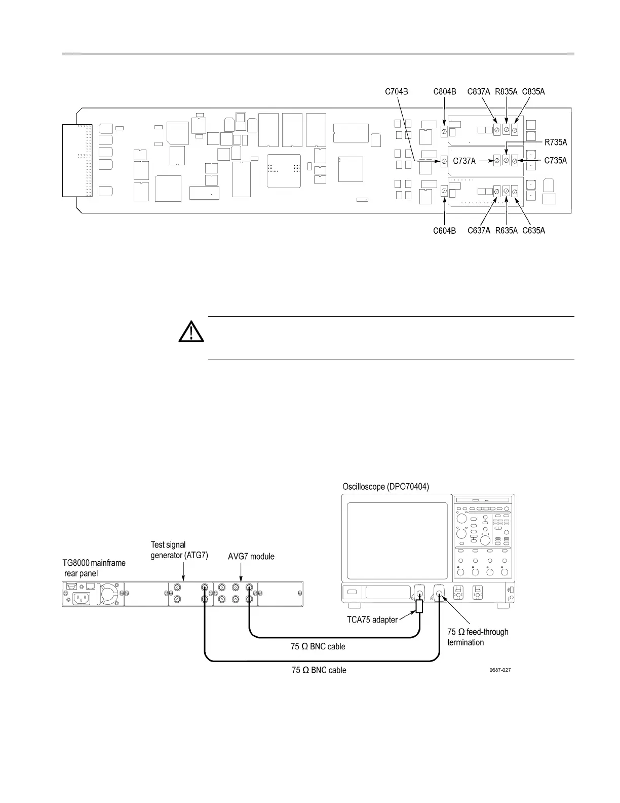
Figure 6-3: Location of the variable resistors and capacitors for the group delay adjustment
Procedure
WARNING. To avoid serious injury, do not touch exposed connectors or
components when operating the TG8000 mainframe with the top cover removed.
Dangerous potentials exist at several points within the TG8000 mainframe.
1. Use the 75 Ω BNC cable and the TCA75 75 Ω signal adapter to connect the
upper CH 1 connector on the AVG7 module to the CH 1 input connector on
the oscilloscope. (See Figure 6-4.)
2. Use the 75 Ω BNC c able and the 75 Ω feed-through termination to connect the
BLACK 1 connector on the test signal generator to the CH 2 input connector
on the oscilloscope. (See Figure 6-4.)
Figure 6-4: E quipment connection for adjusting the group delay
TG8000 Multiformat Test Signal Generator Service Manual 6–7

 Loading...


