AWVG7 module adjustment procedures
Procedure
WARNING. To avoid serious injury, do n ot touch exposed connectors or
components when operating the TG8000 mainframe with the top cover removed.
Dangerous potentials exist at several points within the TG8000 mainframe.
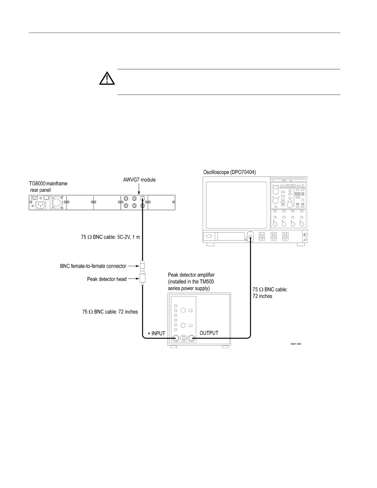
1. Use the two 75 Ω BNC cables, peak detector head, and BNC female-to-female
connector to connect the upper CH 1 connector on the AWVG7 module to the
+INPUT connector on the peak detector amplifier. (See Figure 7-4.)
2. Use the 75 Ω BNC cable to connect the OUTPUT connector on the peak
detector amplifier to the CH 1 input connector on the oscilloscope. (See
Figure 7-4.)
Figure 7-4: Equipment connection for adjusting the frequency response
7–8 TG8000 Multiformat Test Signal Generator Service Manual

 Loading...


