BG7 module adjustment procedures
3. Set the oscillo
scope controls as follows:
Vertical: 100 mV / div
Sample depth: 100 K
Horizontal: 2.5
μs/div
Trigger position: 50%
Vert offset: 700 mV
Trigger: 720 mV, r
ising edge
Hold-off: 63 μs
4. After you see a stable trace on the oscilloscope, change the Vertical setting to
5mV/div.
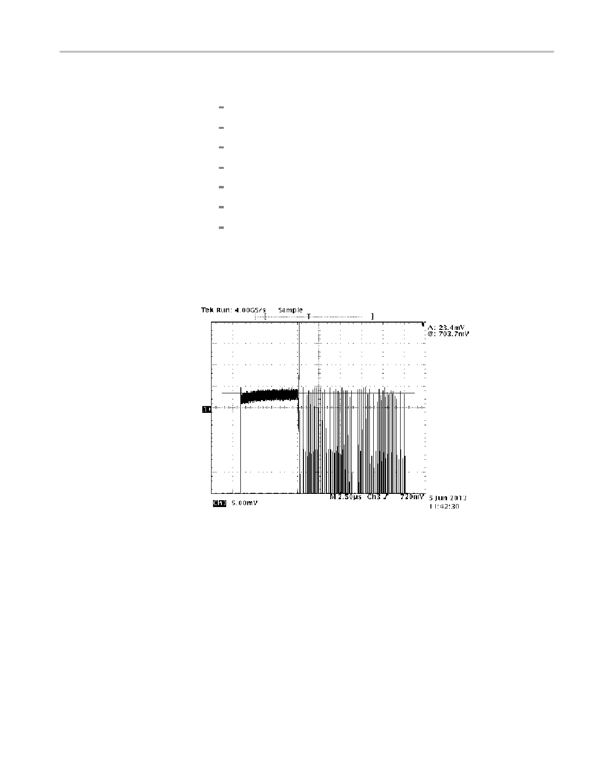
5. Locate the flat bar followed by the burst packets for yellow and cyan as
shown below.
Figure 8-4: Triggered display for adjusting the BG7 module chroma gain
6. Locate variable r
esistor R927 on the BG7 circuit board. (See Figure 8-1.)
7. Adjust R927 to match the level of the first chroma packet to the preceding
75% flat bar.
8. Change the BNC cable connection from the BLACK 3 connector to the
BLACK 4 connector
on the BG7 module.
9. Locate variable resistor R977 on the BG7 circuit board. (See Figure 8-1.)
10. Adjust R977 to match the first chroma packet to the level of the preceding
75% flat bar.
TG8000 Multiformat Test Signal Generator Service Manual 8–7

 Loading...


