BG7 module adjustment procedures
Procedure
WARNING. To avoid serious injury, do n ot touch exposed connectors or
components when operating the TG8000 mainframe with the top cover removed.
Dangerous potentials exist at several points within the TG8000 mainframe.
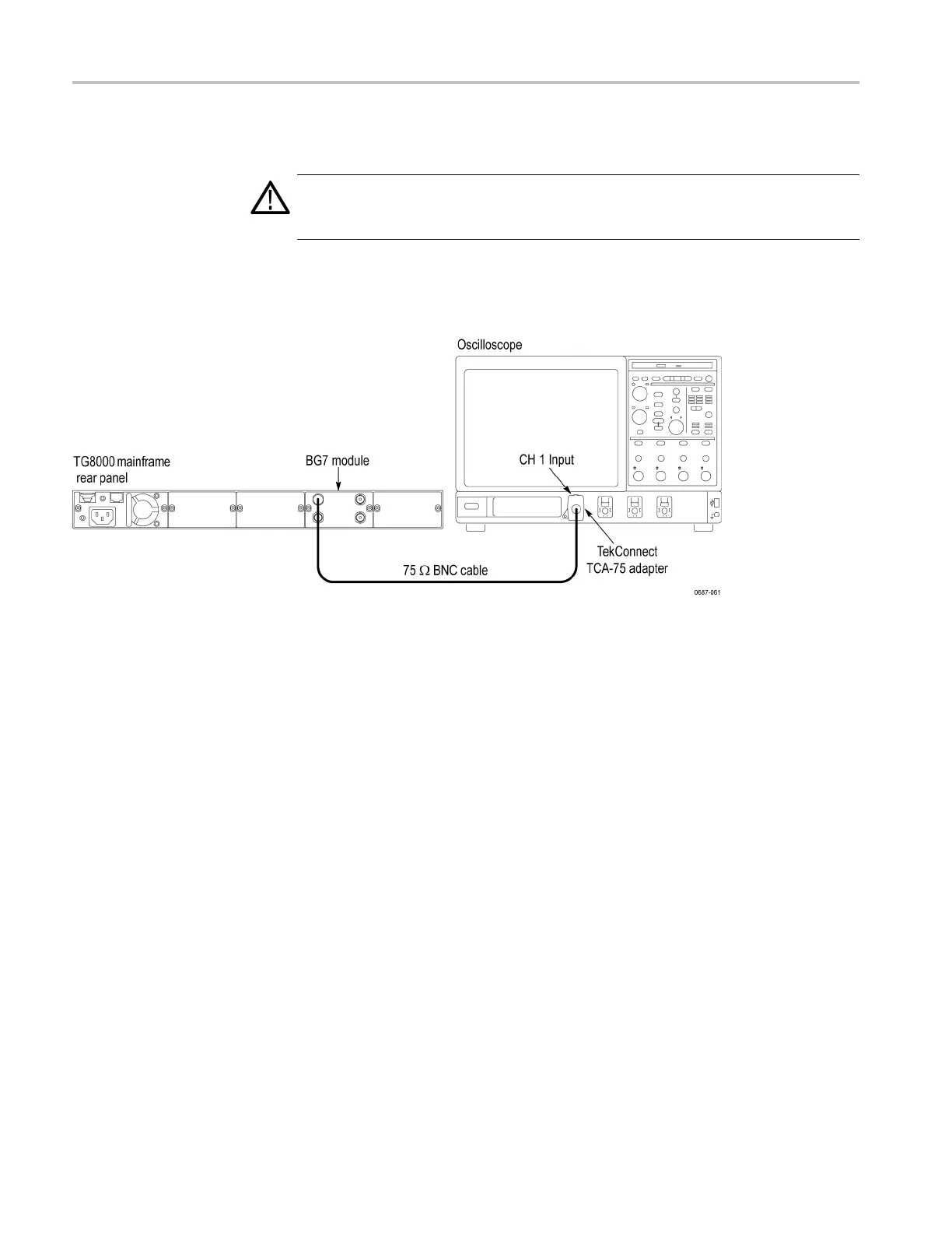
1. Use the 75 Ω BNC cable to connect the BLACK 3 connector on the BG7
Generator module to the CH 1 connector on the oscilloscope. (See Figure 8-3.)
Figure 8-3: Equipment connection for adjusting chroma gain
2. Select the 75% Color Bars (100% White) signal for BLACK 3 and BLACK
4 as follows:
a. Press the MODULE button to display the BG7 main menu.
b. Press the left (◄)orright(►) arrow button to select BLACK 3,andthen
press the ENTER button.
c. Press the left (◄)orright(►)arrowbuttontoselectPAL, and then press
the ENTER button.
d. Press the up (▲)ordown(▼)arrowbuttontoselectTEST SIGNAL.
e. Press the left (◄)orright(►) arrow button to select 75% Color Bars
(100% White), and then press the ENTER button.
f. Press the BACK button twice to return the m odule main menu.
g. Repeat parts b through e of this step to select the 75% Color Bars signal
for BLACK 4.
8–6 TG8000 Multiformat Test Signal Generator Service Manual

 Loading...


