HD3G7 module adjustment procedures
Print this tabl
e for use during the HD3G7 module adjustment procedure.
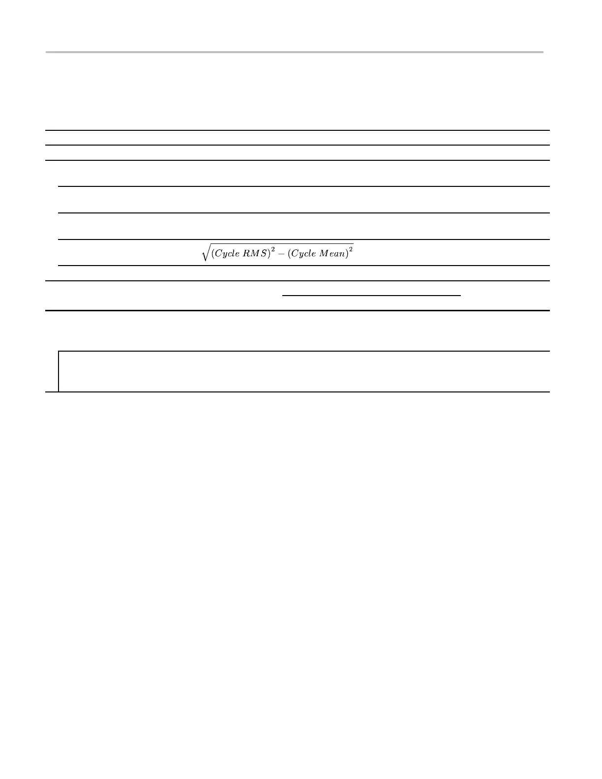
Table 11-2: HD3G7 module SDI output amplitude
Minimum Value Maximum
Characterization
DMM Measurement
(typically 0.2880 V)
—— ——
Oscilloscope Cycle RMS
(typically 116 mV)
—— ——
Oscilloscope Cycle Mean
(typically 1 mV)
—— ——
Sine wave RMS amplitude
(typically 116 mV)
——
Attenuation Factor 2.35 2.55
ValueAdjustment Record
Minimum Before adjustment After adjustment Maximum
Signal 1 amplitude
Measured value (μ)
with attenuation
776 mV 824 mV
Signal 2 amplitude
Measured value (μ)
with attenuation
776 mV 824 mV
11–4 TG8000 Multiformat Test Signal Generator Service Manual

 Loading...


