HD3G7 module removal and replace ment
4. If necessary, p
osition the outer rear panel over the BNC connectors.
5. Install the three P1 Posidriv flathead screws, from the bottom through the
chassis into t
he heat sink. Torque these screws to 5.0 in/lb.
6. Replace the washers and
9
/
16
inch nuts onto the BNC connectors. Torque
these nuts t
o 14.0 in/lb.
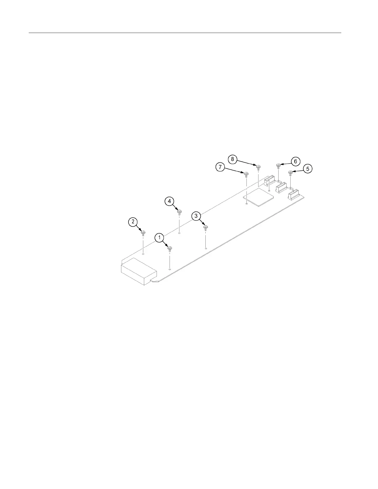
7. Tighten the eight T10 screws that attach the Main circuit board to the chassis
andtothehe
at sink, in the sequence shown below. (See Figure 11-4.) Note
that the two screws that attach the Main board to the heat sink are tightened
last (7 and 8). Torque all these s crews to 8.0 in/lb.
Figure 11-4: HD3G7 module main board installation
The HD3G7 module is now ready to install in the mainframe.
11–24 TG8000 Multiformat Test Signal Generator Service Manual

 Loading...


