SDI7 module troubleshooting
Check the power supplies
The module diag
nostics check most of the power supplies, but there are two that
need manual verification.
1. Remove the TG8
000 top cover. (See page 2-25, Top cover.)
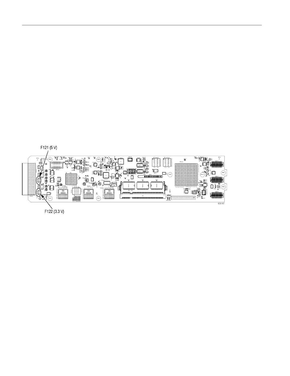
2. Check the +5 V supply by measuring the voltage at F121, which should be in
the range of
+4.75 V to +5.25 V. (See Figure 14-2.) This fuse is located under
one of the mainframe support bars, and is difficult to access.
3. Check the +3
.3 V supply by m easuring the voltage at F122, which should be
in the range of +3.135 V to +3.465 V. (See Figure 14-2.) This fuse is located
under one of the mainframe support bars, and is difficult to access.
Make sure that the voltage is present on both ends of the fuse. If the voltage is
present on only one end of the fuse the module must be replaced. If the voltage
is not present on either end of the fuse, check the mainframe power and the
connector between the module and the mainframe. If they are okay, the mainframe
must be repaired.
Figu
re 14-2: SDI7 power supply test points
14–22 TG8000 Multiformat Test Signal Generator Service Manual

 Loading...


