ELECTRICAL SYSTEM
10C-5
SECTION 10C. GENERAL INSTRUCTIONS
GENERAL
Repair of the electrical system is generally limited to
the replacement of defective components or wiring.
Wiring diagrams and Component Location illustrations
are provided in Section 10L for troubleshooting and
testing the electrical system. Specific repair and
replacement instructions, where applicable, are also
provided.
See the engine manufacturer’s service manual for
information on engine electrical components not
covered in this section.
In addition to testing a suspected faulty component, it
may be necessary to check for shorts or breaks in the
wiring to the component. A common method of testing
wires or circuits is to perform a continuity check as
described below.
If a component (switch, relay, etc.) is removed for test
or replacement, make sure to identify and label all
wires so that the component can be reinstalled cor-
rectly.
USING A MULTIMETER
A multimeter can be used to test electrical systems for
proper operation. This section describes the multimeter
settings used for the various tests performed in the
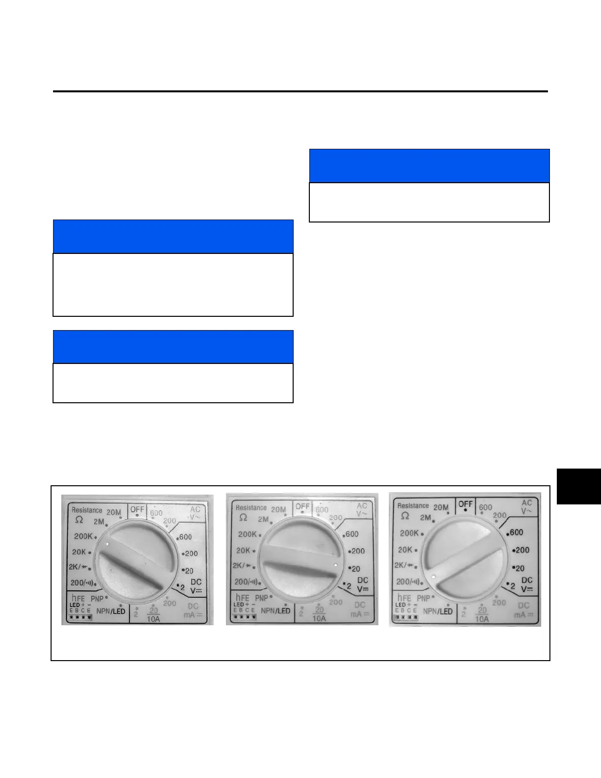
section. Figure 10C-1 shows settings on a typical multi-
meter.The multimeter settings include:
• Resistance (Ohms) – The ability of a material
to oppose the flow of current (amps).
• DC Voltage (VDC) – Used to test the amount of
DC voltage passing through a circuit.
•Continuity (—|) – Test a wire, switch, or other
device to determine if the device has an open
circuit that will not allow current to pass.
Figure 10C-1. Typical Multimeter Settings
NOTICE
The test instrument shown in the illustrations for this
section is a digital multimeter (DMM). However, any
test instrument capable of measuring the current
resistance and continuity values specified is accept-
able.
NOTICE
See the engine manufacturer’s service manual for
information on engine electrical components not cov-
ered in this section.
NOTICE
Before performing any component or wiring
test, check for corrosion and loose or missing
connections.
Resistance (Ohms)
200K Shown
Continuity - Includes Ohms
Reading and Buzzer
DC volts - 20 VDC Shown
10C
 Loading...


