ELECTRICAL SYSTEM
10G-14
c. Hold the ignition switch in the GLOW PLUG
position and connect one test lead to terminal
30 and one lead to terminal 19. Test all pin
positions.
Continuity should be available between termi-
nals 30, AC, and 19.
d. Hold the ignition switch in the START position.
Connect one test lead to terminal 30 and one
lead to terminal 50. Test all pin positions.
Continuity should be available between termi-
nals 30, AC, 50, and 19.
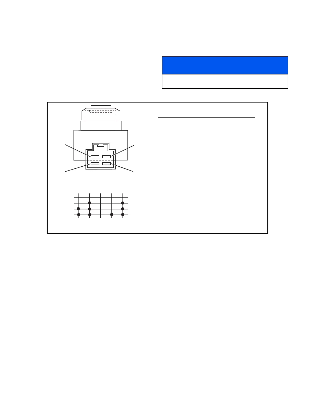
Figure 10G-2. Ignition Switch Test
NOTICE
If the ignition switch fails any of the above tests,
replace the switch.
0
1
2
3
19 30 50 AC
Terminal Number
Position
Connection Diagram
B - 30
1 - AC
S - 50
GP - 19
Position Continuity
0 – OFF None
1 – RUN 30 and AC
2 – Glow Plug 30, AC, and 19
3 – Start 30, AC, 19, and 50
If other terminals test with continuity, the
switch should be replaced.
 Loading...


