ELECTRICAL SYSTEM
10G-13
SECTION 10G. SWITCHES
GENERAL
This section provides instructions for testing the vari-
ous switches in the electrical system. Repair is limited
to replacement of components found faulty during test-
ing. See Section 10M for location of components.
Switches can be defined as NO (normally open) or NC
(normally closed). A normally open switch blocks the
flow of current until the switch is activated. A normally
closed switch allows current to flow until the switch is
activated. Testing a switch allows the mechanic to
determine if the switch actually opens or closes when
activated and if it is activated.
SEAT SWITCH (SW2)
The seat switch allows the engine to run when the
operator is in the seat and the deck is operating. If the
operator leaves or falls from the seat with the engine
running, the engine shuts down.
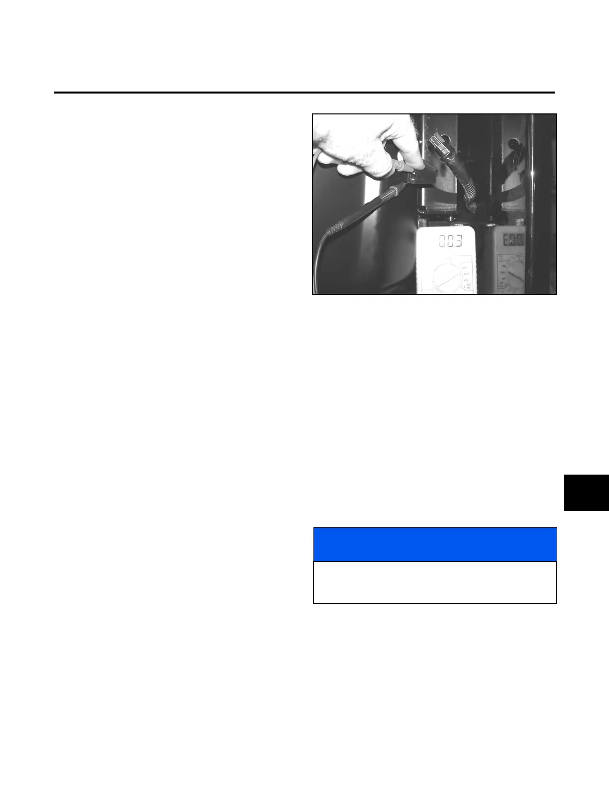
See Figure 10G-1 and test switch as follows:
1. Unplug the switch from the harness.
2. Set the multimeter to the continuity scale.
3. Connect one lead to each side of the seat harness
connector.
The seat switch should be open with no continuity
displayed on the multimeter.
4. Depress the seat switch or have a helper sit in the
seat.
The seat switch should be closed and a reading of
0 to 0.5
(Ohms) should display on the multime-
ter.
NOTE:
Replace the switch if the test results are not satis-
factory.
Figure 10G-1. Seat Test
IGNITION SWITCH (SW1)
1. Disconnect the ground (black) cable at the battery.
2. Remove the steering tower cover.
3. Remove the wiring harness connector from the
ignition switch.
4. Set the multimeter to continuity scale.
5. See Figure 10G-2 and Figure 10G-3 all switch
positions as follows:
a. With the ignition switch in the OFF position,
check all pin positions for continuity.
Continuity should not be available between
any of the pin positions.
b. Place the ignition switch in the RUN position
and connect one test lead to terminal AC and
one lead to terminal 30. Check all pin posi-
tions.
Continuity should be available between termi-
nals 30 and AC.
NOTICE
If a reading of 0.5 (Ohms) or more exists in any of
the following tests, the ignition switch is faulty and
must be replaced.
10G
 Loading...


