ELECTRICAL SYSTEM
10G-17
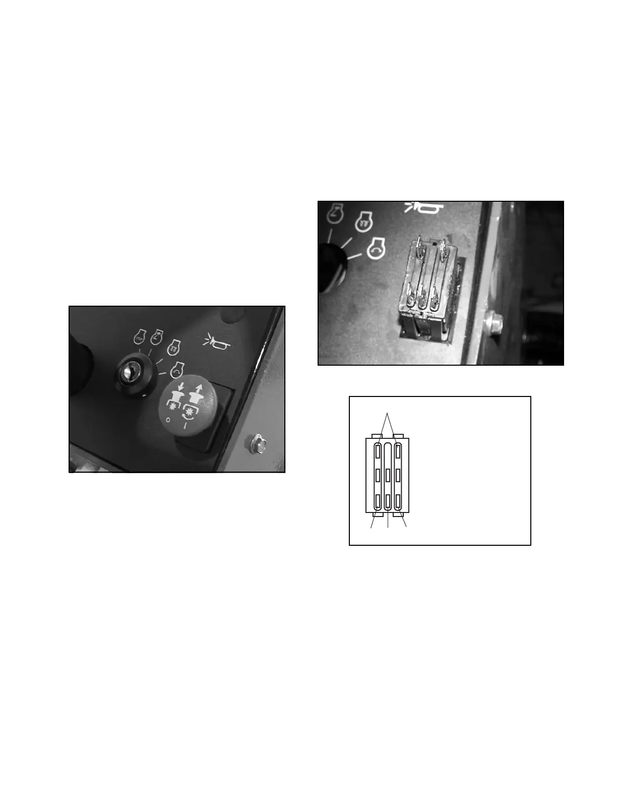
MOW (DECK) SWITCH (SW4)
The mow switch is mounted on the control panel. When
up, a set of contacts are closed. This creates a path for
the movement of current through the switch and to the
mow deck solenoid valve. The deck should be operat-
ing.
1. Shut down the engine and remove the ignition
key.
2. Remove the steering tower cover.
3. Using a multimeter, check for battery voltage at
the orange wire (terminal 4).
Battery voltage should be available at terminal 4.
If not, check the wiring harness for loose, broken,
or dirty connections. In addition, check the inter-
lock system switches for activation and continuity.
Figure 10G-6. Mow (Deck) Switch
4. Remove the wire connector from the switch termi-
nals.
5. Set the multimeter to continuity scale. Place one
test lead on terminal 4 and one test lead on termi-
nal 5. Place the switch in the ON position.
Continuity should be available with the switch in
the ON position. If not, replace the switch.
6. Place one test lead on terminal 4 and one test
lead on terminal 2. Place the switch in the OFF
position.
Continuity should be available with the switch in
the OFF position. If not, replace the switch.
7. Install wire connectors on switch terminals.
Figure 10G-7. Mow (Deck) Switch Terminals
Figure 10G-8. Mow (Deck) Switch Test
Not Used
Switch Down
Continuity 4 and 2
Switch Up
Continuity 4 and 5
452
 Loading...


